 |
am2zzw00005097
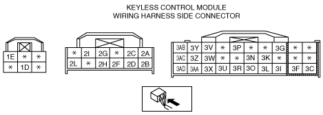
KEYLESS CONTROL MODULE INSPECTION [ADVANCED KEYLESS AND START SYSTEM]
id0914004385b0
1. Remove the glove compartment. (See GLOVE COMPARTMENT REMOVAL/INSTALLATION.)
2. Remove the glove compartment cover. (See GLOVE COMPARTMENT COVER REMOVAL/INSTALLATION.)
3. Measure the voltage according to the terminal voltage table.
Terminal Voltage Table (Reference)
am2zzw00005097
|
|
Terminal |
Signal name |
Connected to |
Measurement condition |
Voltage (V) |
Inspection item(s) |
|
|---|---|---|---|---|---|---|
|
1D
|
Power supply
|
BCM
|
Under any condition
|
B+
|
ROOM 15 A fuse
BCM
Battery
|
|
|
1E
|
Power supply
|
P/W 20 A fuse
|
Under any condition
|
B+
|
P/W 20 A fuse
Battery
|
|
|
2A
|
Power supply
|
MIRROR 7.5 A fuse
|
Ignition switch at ACC position
|
B+
|
Ignition switch
MIRROR 7.5 A fuse
Battery
|
|
|
Ignition switch at LOCK position
|
1.0 or less
|
|||||
|
2B
|
Rx-PATS*1
|
Coil antenna
|
Terminal used for communication therefore determination based on terminal voltage inspection not possible.
|
|||
|
2C
|
Power supply
|
ENG 10 A fuse
|
Ignition switch is at ON position
|
B+
|
Ignition switch
ENG 10 A fuse
Battery
|
|
|
Ignition switch at LOCK position
|
1.0 or less
|
|||||
|
2D
|
Tx-PATS*1
|
Coil antenna
|
Terminal used for communication therefore determination based on terminal voltage inspection not possible.
|
|||
|
2F
|
BCM communication
|
BCM
|
Terminal used for communication therefore determination based on terminal voltage inspection not possible.
|
|||
|
2G
|
HS-CAN+
|
-
|
Terminal used for communication therefore determination based on terminal voltage inspection not possible.
|
|||
|
2H
|
Keyless entry communication
|
Keyless receiver
|
Terminal used for communication therefore determination based on terminal voltage inspection not possible.
|
|||
|
2I
|
HS-CAN-
|
-
|
Terminal used for communication therefore determination based on terminal voltage inspection not possible.
|
|||
|
2L
|
Steering lock unit communication
|
Steering lock unit
|
Terminal used for communication therefore determination based on terminal voltage inspection not possible.
|
|||
|
3C
|
Keyless antenna (exterior, rear)
|
Keyless antenna (exterior, rear)
|
Terminal used for communication therefore determination based on terminal voltage inspection not possible.
|
|||
|
3F
|
Keyless antenna (LF)
|
Keyless antenna (LF)
|
Terminal used for communication therefore determination based on terminal voltage inspection not possible.
|
|||
|
3G
|
Liftgate unlock input*2/Trunk lid unlock input*3
|
Liftgate opener switch*2/Trunk lid opener switch*3
|
Liftgate opener switch/Trunk lid opener switch pressed
|
3.0
|
Liftgate opener switch*2/Trunk lid opener switch*3
|
|
|
Liftgate opener switch/Trunk lid opener switch released
|
4.7
|
|||||
|
3I
|
Keyless antenna (interior, rear)
|
Keyless antenna (interior, rear)
|
Terminal used for communication therefore determination based on terminal voltage inspection not possible.
|
|||
|
3K
|
Keyless beeper power supply
|
Keyless beeper
|
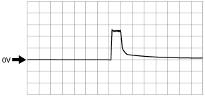
Exterior keyless beeper sounds (transmitter lock button pressed)
|
Wave pattern (See Pattern 1.)
|
Keyless beeper
|
|
|
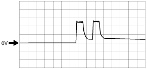
Exterior keyless beeper sounds (transmitter unlock button pressed)
|
Wave pattern (See Pattern 2.)
|
|||||
|
Other
|
1.0 or less
|
|||||
|
3L*3
|
Keyless antenna (interior, center)
|
Keyless antenna (interior, center)
|
Terminal used for communication therefore determination based on terminal voltage inspection not possible.
|
|||
|
3N
|
GND
|
Body ground
|
Under any condition
|
1.0 or less
|
Ground
|
|
|
3O
|
Keyless antenna (RF)
|
Keyless antenna (RF)
|
Terminal used for communication therefore determination based on terminal voltage inspection not possible.
|
|||
|
3P
|
Lock input
|
Door lock-link switch (driver's door)
|
Driver's side door lock switch at LOCK
|
1.0 or less
|
Door lock-link switch
|
|
|
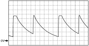
Driver's side door lock switch at UNLOCK
|
Wave pattern (See Pattern 3.)
|
|||||
|
3R
|
Keyless antenna (interior, front)
|
Keyless antenna (interior, front)
|
Terminal used for communication therefore determination based on terminal voltage inspection not possible.
|
|||
|
3U
|
Request switch input (RF)
|
Request switch (RF)
|
Outer handle (RF) side request switch ON
|
1.0 or less
|
Front outer handle (RF)
|
|
|
Outer handle (RF) side request switch OFF
|
B+
|
|||||
|
3V
|
Start knob (push switch)
|
Steering lock unit
|
Push switch in pressed condition
|
B+
|
Steering lock unit
|
|
|
Other
|
1.0 or less
|
|||||
|
3W
|
Key reminder switch
|
Steering lock unit
|
Key inserted in steering lock
|
B+
|
Steering lock unit
|
|
|
Other
|
1.0 or less
|
|||||
|
3X
|
Request switch input (LF)
|
Request switch (LF)
|
Outer handle (LF) side request switch ON
|
1.0 or less
|
Front outer handle (LF)
|
|
|
Outer handle (LF) side request switch OFF
|
B+
|
|||||
|
3Y*3
|
Keyless antenna (interior, center)
|
Keyless antenna (interior, center)
|
Terminal used for communication therefore determination based on terminal voltage inspection not possible.
|
|||
|
3Z
|
Keyless antenna (interior, rear)
|
Keyless antenna (interior, rear)
|
Terminal used for communication therefore determination based on terminal voltage inspection not possible.
|
|||
|
3AA
|
Keyless antenna (interior, front)
|
Keyless antenna (interior, front)
|
Terminal used for communication therefore determination based on terminal voltage inspection not possible.
|
|||
|
3AB
|
Keyless antenna (LF)
|
Keyless antenna (LF)
|
Terminal used for communication therefore determination based on terminal voltage inspection not possible.
|
|||
|
3AC
|
Keyless antenna (exterior, rear)
|
Keyless antenna (exterior, rear)
|
Terminal used for communication therefore determination based on terminal voltage inspection not possible.
|
|||
|
3AD
|
Keyless antenna (RF)
|
Keyless antenna (RF)
|
Terminal used for communication therefore determination based on terminal voltage inspection not possible.
|
|||
Generated pulse (reference)
Pattern 1
am2zzw00005101
|
Pattern 2
am2zzw00005102
|
Pattern 3
am2zzw00004150
|