FRONT COMBINATION LIGHT [WITH LED HEADLIGHT]
id0918000102b9
Purpose
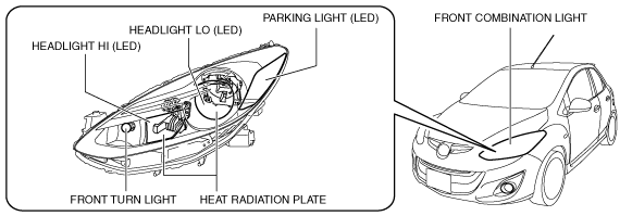
• Parts related to the front exterior lights are grouped and housed together such as the headlights, parking light, front turn light, and wiring harnesses, or connectors.
• The following has been achieved with the adoption of LEDs on the headlights (LO/HI)
-
― Reduced power consumption of headlights
― Reduced weight of front combination lights contributes to improved fuel economy
― Headlights have become maintenance-free
― Wider light distribution of headlights improves visibility
Function
• Each light is illuminated or flashed when the light switch, turn switch, or hazard warning switch is operated.
Outer lens temperature control function
-
• Poor visibility due to snow accumulation on the headlight lenses is prevented by melting the snow on the headlight outer lens (LO/HI) using the heat generated by the LEDs. A furrow set in the housing inside the front combination light channels the heat absorbed by the heat radiation plate installed on the back of the headlight (LO) reflector to the outer lens, raising the temperature of the outer lens.
Construction
• The following parts are an integrated structure.
-
― Headlight LO (LED)
― Headlight HI (LED)
― Parking light (LED)
― Front turn light
-
Note
-
• Fogging or condensation on the inside of the front combination lights may occur, however, it is a natural phenomenon occurring as a result of a temperature difference between the interior and exterior of the front combination lights and does not affect the light performance.
• Fogging or condensation occurring as a natural phenomenon will dissipate when the temperature inside the front combination lights rises after the headlights are illuminated and a period of time has elapsed.
• Heat generated by the illumination of the LEDs is absorbed and dispersed by the heat radiation plates installed to the back of the headlight LO (LED) and headlight HI (LED) reflectors.
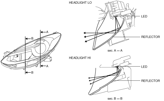
• The optimized shape of the headlight LO and HI reflectors radiates light over a wide area.
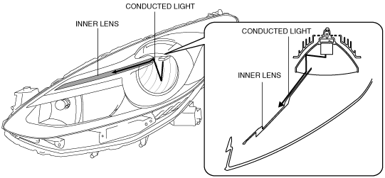
• When the headlights are illuminated, light from the headlight LO is conducted to the inner lens positioned inside the front combination light, illuminating the entire surface of the inner lens.
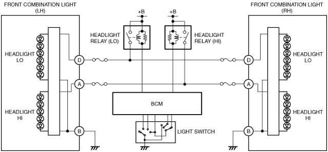
System Wiring Diagram
Operation
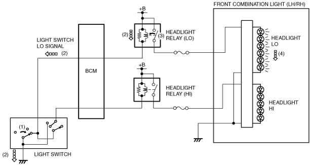
Headlight LO
-
1. When the light switch is turned to HEAD position (1), the light switch LO signal (2) is transmitted to the BCM and body ground via the light switch.
2. When the light switch LO signal is transmitted to body ground, the headlight relay (LO) is turned ON (3).
3. When the headlight relay (LO) is turned ON, the headlights LO (4) are illuminated.
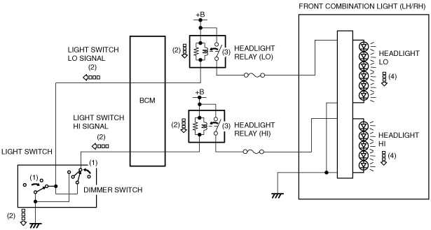
Headlight HI
-
1. When the light switch is turned to HEAD, and the dimmer switch is in the HI position (1), the light switch LO and light switch HI signals (2) are transmitted to the BCM, and to body ground via the light switch.
2. When the light switch LO signal is transmitted to body ground, the headlight relay (LO) and headlight relay (HI) are turned ON (3).
3. When the headlight relay (LO) and headlight relay (HI) are turned ON, the headlight LO and headlight HI (4) are illuminated.
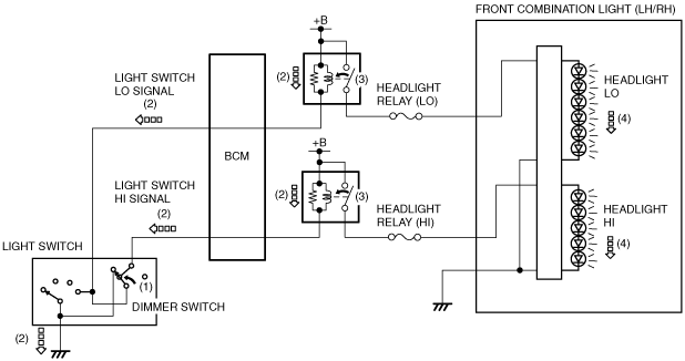
Passing
-
1. When the dimmer switch is turned to the flashing position (1), the light switch LO signal and light switch HI signal (2) are transmitted to the BCM, and body ground via the light switch.
2. When the light switch LO signal is transmitted to body ground, the headlight relay (LO) and headlight relay (HI) are turned ON (3).
3. When the headlight relay (LO) and headlight relay (HI) are turned ON, the headlight LO and headlight HI (4) are illuminated.
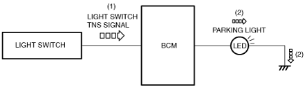
Parking light
-
1. When the light switch is operated to the TNS position, a light switch TNS signal is input to the BCM.
2. When the BCM receives the light switch TNS signal, the parking lights are illuminated.
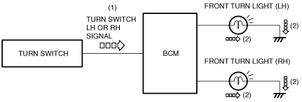
Front turn light (turn light system)
-
1. When the turn switch is operated to the LH or RH position, a turn switch LH or RH signal is input to the BCM.
2. When the BCM receives the turn switch LH or RH signal, the front turn light (LH) or (RH) flashes.
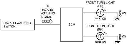
Front turn lights (hazard system)
-
1. When the hazard warning switch is turned on, the hazard warning signal is input to the BCM.
2. When the BCM receives the hazard warning signal, the front turn lights (RH) and (LH) flash.
Fail-safe
• Not applicable