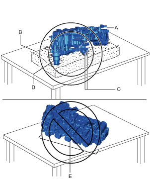
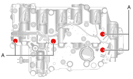
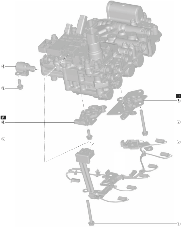
CONTROL VALVE BODY DISASSEMBLY


id051700661400


Structural view

bcw6ja00000163

1
4 bolts
2
Coupler component
3
Bolt
4
ON/OFF solenoid
5
3 bolts
6
Oil pressure switch B
7
4 bolts
8
Oil pressure switch A


Disassembly Procedure

Caution
•  Disassemble the control valve body and replace the malfunctioning part only if there is a malfunction in the control valve body determined by the troubleshooting procedure and using the vehicle diagnostic tester (M-MDS).
However, if there is a malfunction in the parts other than the following, replace the control valve body with a new one because the parts other than the following are not shipped from the factory as a single component.
―  ON/OFF solenoid
―  Oil pressure switch A
―  Oil pressure switch B
―  Coupler component
•  Do not drop or apply a shock to the control valve body. Replace the control valve body with a new one if it was dropped or received an impact.
•  If the control valve body is placed with the shift solenoid side facing down on a workbench, the wiring harness or connector of the coupler component may be damaged. When placing the control valve body on a workbench, always place it with the control valve body connector side facing down. However, if the control valve body is directly placed on the workbench, the control valve body connector area or the sensor may be damaged. Always place the control valve body on an impact-absorbing material, which is free of foreign matter, so that the connector area and the sensor do not contact the workbench directly.
bcw6ja00000597
A: Control valve body
B: Impact-absorbing material which is free of foreign matter
C: Sensor
D: Control valve body connector
E: Shift solenoid
•  Touching the ATF temperature sensor element or the lead wires by hand may cause a malfunction. When handling the coupler component, do not touch the ATF temperature sensor element or the lead wires.
bcw6ja00000027
A: Lead wire
B: Element
C: ATF temperature sensor

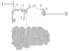
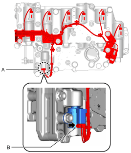
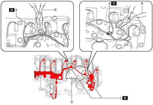
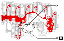
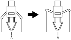
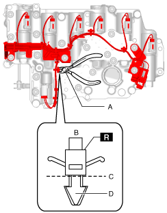
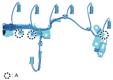
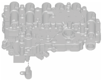
1.  Remove the coupler component using the following procedure.

bcw6ja00000283

1
4 bolts
2
Coupler component

(1)  Release the connector tab shown in the figure and disconnect the connector.
bcw6ja00000065
A  :Connector
B  :Tab
Caution
•  When disconnecting the connector, pulling the wiring harness may cause poor contact, do not pull the wiring harness. Disconnect the connector by pulling the connector part straight with the connector tab released.
(2)  Loosen the bolts shown in the figure.
bcw6ja00000066
A  :Bolt
Note
•  The connector can be disconnected easily by loosening the bolts.
(3)  Release the ON/OFF solenoid connector tab and disconnect the ON/OFF solenoid connector.
bcw6ja00001030
A  :ON/OFF solenoid connector
B  :Tab
(4)  Move the precision flathead screwdriver in the direction of the arrows shown in the figure, and disconnect the shift solenoid connector and oil pressure switch connector.
bcw6ja00000068
A  :Shift solenoid connector
B  :Oil pressure switch connector
C  :Precision flathead screwdriver
Caution
•  Do not scratch the shift solenoid, shift solenoid connector, oil pressure switch and oil pressure switch connector with the precision flathead screwdriver.
•  When disconnecting the connectors, pulling the wiring harness may cause poor connection, do not pull the wiring harness.
(5)  Using pliers, detach the tie wrap clips secured to oil pressure switch A.
bcw6ja00000069
A  :Clip
B  :Pliers
C  :Tie wrap
D  :Oil pressure switch A
(6)  Using the following procedure, remove the tie wrap clip secured to the oil pressure switch B.
bcw6ja00000070
A  :Oil pressure switch B
B  :Tie wrap
1)  Using pliers, pull up the A part of the tie wrap.
bcw6ja00000071
2)  Using nippers, cut and remove the tie wrap.
bcw6ja00000072
A  :Nippers
B  :Tie wrap
C  :Cut
D  :Clip
Caution
•  Collect and dispose of the cut tie wrap clip and its fragments securely.
(7)  Remove the coupler component.
bcw6ja00000066
A  :Bolt
Caution
•  The pins for securing the solenoid valves are located in the areas circled with dotted lines, and they may drop down and be lost during coupler component removal.When removing the coupler component, be careful not to drop the pins for securing the solenoid valves, and if they do drop, be careful that they do not get lost.
bcw6ja00000073
A  :Solenoid valve securing pin position

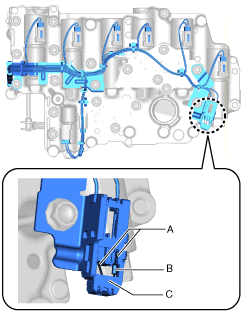
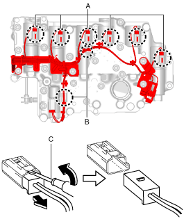
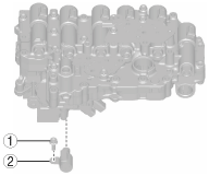
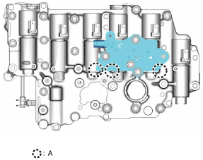
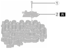
2.  Remove the ON/OFF solenoid using the following procedure:

bcw6ja00000284

1
Bolt
2
ON/OFF solenoid

(1)  Remove the bolts shown in the figure.
bcw6ja00000285
(2)  Remove the ON/OFF solenoid.
bcw6ja00000286

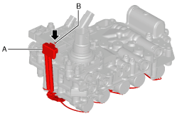
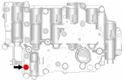
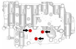
3.  Remove oil pressure switch B using the following procedure:

bcw6ja00000287

1
3 bolts
2
Oil pressure switch B

(1)  Remove the bolts shown in the figure.
bcw6ja00000288
(2)  Remove oil pressure switch B.
bcw6ja00000289

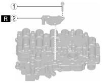
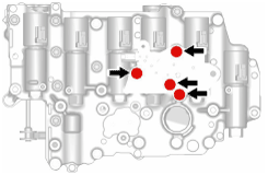
4.  Remove oil pressure switch A using the following procedure:

Caution
•  The pins for securing the solenoid valves are located in the areas circled with dotted lines, and they may drop down and be lost during oil pressure switch A removal.When removing oil pressure switch A, be careful not to drop the pins for securing the solenoid valves, and if they do drop, be careful that they do not get lost.
•  Never change the shift solenoid assembly position. If the assembly position is changed, it may cause a malfunction.
bcw6ja00001031
A  :Solenoid valve securing pin position
bcw6ja00000290

1
4 bolts
2
Oil pressure switch A

(1)  Remove the bolts shown in the figure.
bcw6ja00000291
(2)  Remove oil pressure switch A.
bcw6ja00000292