 |
bcw6ja00000032
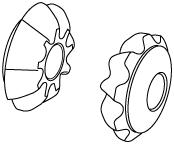
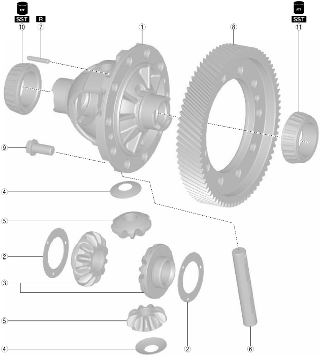
RING GEAR AND DIFFERENTIAL ASSEMBLY
id051700664100
Structural view
bcw6ja00000032
|
|
1
|
Differential gear case
|
|
2
|
Thrust washer (selection)
|
|
3
|
Side gear
|
|
4
|
Thrust washer
|
|
5
|
Pinion gear
|
|
6
|
Pinion shaft
|
|
7
|
Roll pin
|
|
8
|
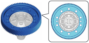
Ring gear
|
|
9
|
10 Bolts (M11 x 1.0 bolt, length approx. 24 mm {0.94 in})
|
|
10
|
Tapered roller bearing (converter housing side)
(inner diameter approx. 40 mm {1.6 in})
|
|
11
|
Tapered roller bearing (transaxle case side)
(inner diameter approx. 40 mm {1.6 in})
|
Assembly Procedure
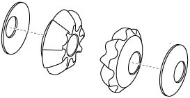
1. Assemble the thrust washers to the side gears.
azzjjw00001535
|
azzjjw00001536
|
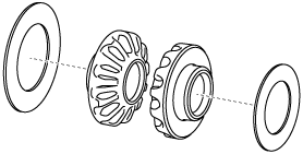
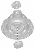
2. Assemble the side gears which have the thrust washers assembled to them.
bcw6ja00000153
|
bcw6ja00000277
|
3. Assemble the thrust washers to the pinion gears.
azzjjw00001539
|
azzjjw00001540
|
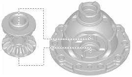
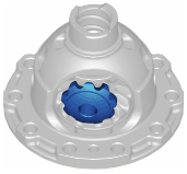
4. Assemble the pinion gears which have the thrust washers assembled to them using the following procedure:
bcw6ja00000152
|
bcw6ja00000278
|
bcw6ja00000246
|
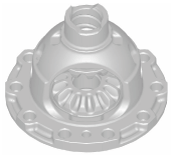
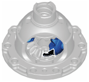
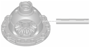
5. Assemble the pinion shaft.
bcw6ja00000150
|
bcw6ja00000247
|
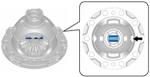
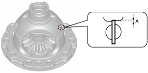
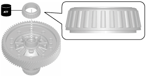
6. Assemble a new roll pin to the position shown in the figure using a pin punch.
bcw6ja00000034
|
bcw6ja00000035
|
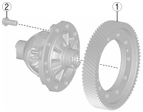
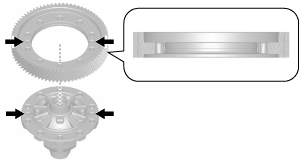
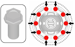
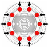
7. Assemble the ring gear using the following procedure:
bcw6ja00000248
|
|
1
|
Ring gear
|
|
2
|
10 Bolts (M11 x 1.0 bolt, length approx. 24 mm {0.94 in})
|
bcw6ja00000212
|
bcw6ja00000213
|
bcw6ja00000214
|
azzjjw00001004
|
bcw6ja00000249
|
azzjjw00001006
|
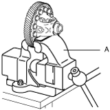
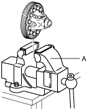
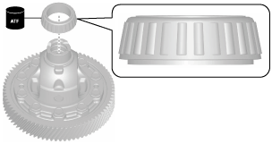
8. Assemble the tapered roller bearing (converter housing side) using the following procedure:
bcw6ja00000036
|
bcw6ja00001050
|
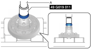
9. Assemble the tapered roller bearing (transaxle case side) using the following procedure:
bcw6ja00000038
|
bcw6ja00001147
|
10. Perform the differential backlash measurement/adjustment. (See DIFFERENTIAL BACKLASH MEASUREMENT/ADJUSTMENT.)