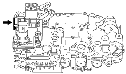
CONTROL VALVE BODY ASSEMBLY
id051700664300
Structural view
|
1
|
Oil pressure switch A
|
|
2
|
3 Bolts (M6 x 1.0 bolt, length approx. 55 mm {2.2 in})
1 bolt (M6 x 1.0 bolt, length approx. 16 mm {0.63 in})
|
|
3
|
Oil pressure switch B
|
|
4
|
1 Bolt (M6 x 1.0 bolt, length approx. 70 mm {2.8 in})
1 Bolt (M6 x 1.0 bolt, length approx. 35 mm {1.4 in})
1 bolt (M6 x 1.0 bolt, length approx. 16 mm {0.63 in})
|
|
5
|
ON/OFF solenoid
|
|
6
|
1 bolt (M6 x 1.0 bolt, length approx. 16 mm {0.63 in})
|
|
7
|
Coupler component
|
|
8
|
2 Bolts (M6 x 1.0 bolt, length approx. 55 mm {2.2 in}
2 bolts (M6 x 1.0 bolt, length approx. 16 mm {0.63 in})
|
Assembly Procedure
-
Caution
-
• Do not drop or apply a shock to the control valve body. Replace the control valve body with a new one if it was dropped or received an impact.
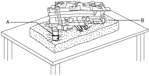
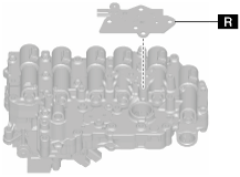
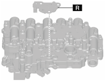
1. As shown in the figure, place the control valve body with the TCM side pointing downward on an impact-absorbing material which is free of foreign matter.
-
Caution
-
• If the control valve body is placed with the shift solenoid side facing down on a workbench, the wiring harness or connector of the coupler component may be damaged. When placing the control valve body on a workbench, always place it with the control valve body connector side facing down. However, if the control valve body is directly placed on the workbench, the control valve body connector area or the sensor may be damaged. Always place the control valve body on an impact-absorbing material, which is free of foreign matter, so that the connector area and the sensor do not contact the workbench directly.
A: Control valve body
B: Impact-absorbing material which is free of foreign matter
C: Sensor
D: Control valve body connector
E: Shift solenoid
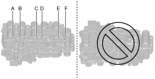
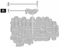
• If the control valve body is placed on the workbench with the TCM side pointing upward, the pins securing the solenoids shown in the figure could fall off and become lost.
If the solenoid installation position shown in the figure is changed, it will cause a malfunction.
To prevent the pin securing the solenoid from falling, always place the control valve body on an impact-absorbing material, which is free of foreign matter, with the TCM side pointing downward until the coupler component is assembled.
A :TCM
B :Impact-absorbing material which is free of foreign matter
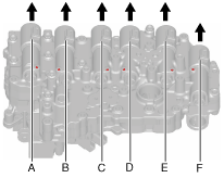
A :Shift solenoid No.1
B :Shift solenoid No.4
C :TCC control solenoid
D :Shift solenoid No.3
E :Shift solenoid No.2
F :Pressure control solenoid
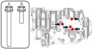
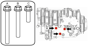
2. Verify that the pins securing the pressure control solenoid, TCC control valve, and each shift solenoid are not removed using the following procedure:
- (1) Pull each solenoid in the direction of the arrow shown in the figure and verify that it is secured.
-
A :Shift solenoid No.1
B :Shift solenoid No.4
C :TCC control solenoid
D :Shift solenoid No.3
E :Shift solenoid No.2
F :Pressure control solenoid
-
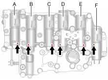
• If there is a malfunction, assemble the pin securing the solenoid to the malfunctioning part.
A :Shift solenoid No.1
B :Shift solenoid No.4
C :TCC control solenoid
D :Shift solenoid No.3
E :Shift solenoid No.2
F :Pressure control solenoid
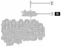
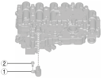
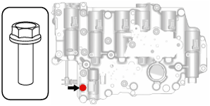
3. Assemble the oil pressure switch A using the following procedure:
|
1
|
Oil pressure switch A
|
|
2
|
3 Bolts (M6 x 1.0 bolt, length approx. 55 mm {2.2 in})
1 bolt (M6 x 1.0 bolt, length approx. 16 mm {0.63 in})
|
- (1) Assemble the oil pressure switch A.
-
- (2) Assemble and tighten the bolts shown in the figure.
-
A :Bolt (M6 x 1.0 bolt, length approx. 55 mm {2.2 in})
B :Bolt (M6 x 1.0 bolt, length approx. 16 mm {0.63 in})
-
Tightening torque
-
9—10 N·m {92—101 kgf·cm, 80—88 in·lbf}
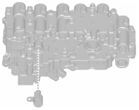
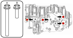
4. Assemble the oil pressure switch B using the following procedure:
|
1
|
Oil pressure switch B
|
|
2
|
1 Bolt (M6 x 1.0 bolt, length approx. 70 mm {2.8 in})
1 Bolt (M6 x 1.0 bolt, length approx. 35 mm {1.4 in})
1 bolt (M6 x 1.0 bolt, length approx. 16 mm {0.63 in})
|
- (1) Assemble the oil pressure switch B.
-
- (2) Assemble and tighten the bolts shown in the figure.
-
A :Bolt (M6 x 1.0 bolt, length approx. 70 mm {2.8 in})
B :Bolt (M6 x 1.0 bolt, length approx. 35 mm {1.4 in})
C :Bolt (M6 x 1.0 bolt, length approx. 16 mm {0.63 in})
-
Tightening torque
-
9—10 N·m {92—101 kgf·cm, 80—88 in·lbf}
5. Assemble the ON/OFF solenoid using the following procedure:
|
1
|
ON/OFF solenoid
|
|
2
|
Bolt (M6 x 1.0 bolt, length approx. 16 mm {0.63 in})
|
- (1) Assemble the ON/OFF solenoid.
-
- (2) Assemble and tighten the bolts shown in the figure.
-
-
Note
-
• Bolt size: M6 x 1.0 bolt, length approx. 16 mm {0.63 in}
-
Tightening torque
-
9—10 N·m {92—101 kgf·cm, 80—88 in·lbf}
6. Assemble the coupler component using the following procedure:
|
1
|
Coupler component
|
|
2
|
2 Bolts (M6 x 1.0 bolt, length approx. 55 mm {2.2 in})
2 bolts (M6 x 1.0 bolt, length approx. 16 mm {0.63 in})
|
- (1) Assemble the coupler component.
-
- (2) Connect the oil pressure switch connectors and shift solenoid connectors.
-
A :Shift solenoid connectors
B :Oil pressure switch connectors
-
Caution
-
• Insert the connector until a click is heard.
- (3) Connect the ON/OFF solenoid connector.
-
A :ON/OFF solenoid connector
-
Caution
-
• Insert the connector until a click is heard.
- (4) Install the coupler component.
-
A :Bolt (M6 x 1.0 bolt, length approx. 55 mm {2.2 in})
B :Bolt (M6 x 1.0 bolt, length approx. 16 mm {0.63 in})
-
Caution
-
• When tightening the bolts, be careful not to pinch the coupler component wiring harness. If the wiring harness is pinched, replace the coupler component.
-
Tightening torque
-
9—10 N·m {92—101 kgf·cm, 80—88 in·lbf}
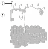
- (5) Assemble new tie wrap clips.
-
A :Clips
B :Tie wraps
-
Caution
-
• Assemble the tie wrap clips in the direction shown in the figure.
• Verify that the tie wrap clips are assembled to the control valve body securely.
• Be careful not to let the coupler component wiring harness contact the surrounding parts.
• Do not twist the coupler component wiring harness.
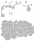
- (6) Connect the connectors shown in the figure.
-
-
Caution
-
• When connecting a connector, insert it at a straight angle until it is securely locked.