 |
bf62zm00000001
TRANSAXLE DISASSEMBLY
id051500168100
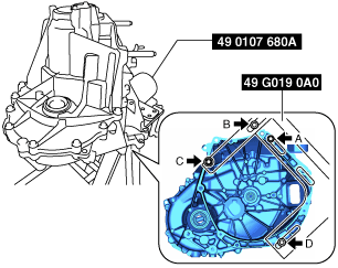
Step 1
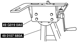
1. Assemble the SST (49 G019 0A0) to the SST (49 0107 680A).
bf62zm00000001
|
2. Assemble the MTX to the SST (49 G019 0A0).
bf62zm00000002
|
3. Remove the parts around the transaxle in the order shown in the figure.
bf62zm00000003
|
|
1
|
Stud bolt
|
|
2
|
Plug
|
|
3
|
Gasket
|
|
4
|
Spring
|
|
5
|
Detent ball
|
|
6
|
Neutral switch No.1
|
|
7
|
Gasket
|
|
8
|
Shift lever shaft anchor bolt
|
|
9
|
Gasket
|
|
10
|
Neutral switch No.2 (with i-stop)
|
|
11
|
Gasket (with i-stop)
|
|
12
|
Back-up light switch
|
|
13
|
Gasket
|
|
14
|
Oil level plug
|
|
15
|
Gasket
|
|
16
|
Reverse idler shaft anchor bolt
|
|
17
|
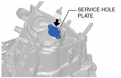
Service hole plate
|
|
18
|
Oil seal
|
|
19
|
Plug
|
|
20
|
Gasket
|
|
21
|
Spring
|
|
22
|
Pin
|
|
23
|
Drain plug
|
|
24
|
Gasket
|
Service hole plate removal note
1. Remove the service hole plate while lightly tapping the side of the service hole plate using a cloth-wrapped flathead screwdriver.
bf62zm00000004
|
Step 2
1. Disassemble the transaxle in the order shown in the figure.
bf62zm00000005
|
|
1
|
Transaxle case component
|
|
2
|
Shim
|
|
3
|
Magnet
|
|
4
|
Control set
|
|
5
|
Reverse lever component
|
|
6
|
Shift rod
|
|
7
|
Shift rod end
|
|
8
|
Shift fork
|
|
9
|
Spring
|
|
10
|
Reverse gate
|
|
11
|
Reverse idler shaft
|
|
12
|
Reverse idler gear
|
|
13
|
Primary shaft component
|
|
14
|
Secondary shaft component
|
|
15
|
Differential
|
|
16
|
Clutch housing component
|
2. Remove the silicone sealant of the transaxle case component and clutch housing component, and clean all the parts.
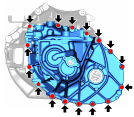
Transaxle case component removal note
1. Remove the transaxle case component installation bolts.
bf62zm00000006
|
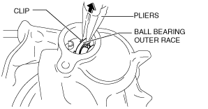
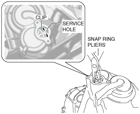
2. While pulling up the ball bearing outer race using pliers as shown in the figure, turn the clip to align the clip opening with the service hole.
bf62zm00000007
|
3. Keep apart the pliers from the ball bearing outer race.
4. Insert the snap ring pliers into the service hole, widen the clip, and disconnect the secondary shaft component from the transaxle case.
bf62zm00000008
|
5. Align the select lever with the positioning mark and set it to the reverse position.
bf62zm00000009
|
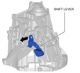
6. Pull the shift lever in the direction shown in the figure.
bf62zm00000010
|
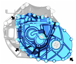
7. Tap the locations shown in the figure using a plastic hammer to remove the transaxle case component.
bf62zm00000011
|
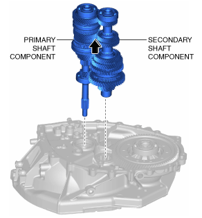
Primary shaft component, secondary shaft component removal note
1. Remove the primary shaft component and secondary shaft component as a single unit.
bf62zm00000012
|