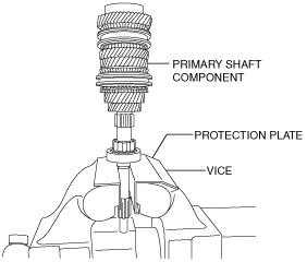
PRIMARY SHAFT COMPONENT PREINSPECTION


id051500168600


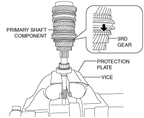
3rd Gear Thrust Clearance Inspection

1.  Secure the primary shaft component in the vice.

bf62zm00000023

Caution
•  Insert a protective plate between the vice and the part so as not to damage the part.

2.  Set the dial gauge to the position of the arrow shown in the figure.

bf62zm00000024

3.  Move the 3rd gear in the axial direction and measure the 3rd gear thrust clearance.

•  If it exceeds the maximum, inspect the 3rd gear and surrounding parts for damage and wear and replace the malfunctioning part.
3rd gear thrust clearance
Specification: 0.208 mm {0.0082 in}
Maximum: 0.300 mm {0.0118 in}


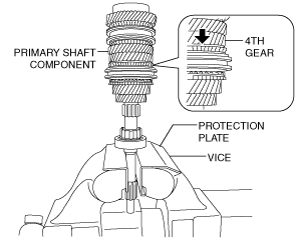
4th Gear Thrust Clearance Inspection

1.  Secure the primary shaft component using a vice.

bf62zm00000023

Caution
•  Insert a protective plate between the vice and the part so as not to damage the part.

2.  Set the dial gauge to the position of the arrow shown in the figure.

bf62zm00000025

3.  Move the 4th gear in the axial direction and measure the 4th gear thrust clearance.

•  If it exceeds the maximum, inspect the 4th gear and surrounding parts for damage and wear and replace the malfunctioning part.
4th gear thrust clearance
Specification: 0.295 mm {0.0116 in}
Maximum: 0.373 mm {0.0147 in}


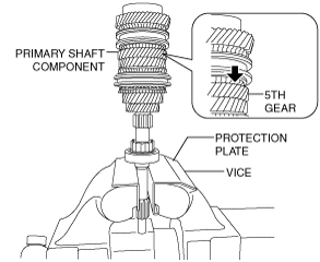
5th Gear Thrust Clearance Inspection

1.  Secure the primary shaft component using a vice.

bf62zm00000023

Caution
•  Insert a protective plate between the vice and the part so as not to damage the part.

2.  Set the dial gauge to the position of the arrow shown in the figure.

bf62zm00000026

3.  Move the 5th gear in the axial direction and measure the 5th gear thrust clearance.

•  If it exceeds the maximum, inspect the 5th gear and surrounding parts for damage and wear and replace the malfunctioning part.
5th gear thrust clearance
Specification: 0.269 mm {0.0106 in}
Maximum: 0.381 mm {0.0150 in}


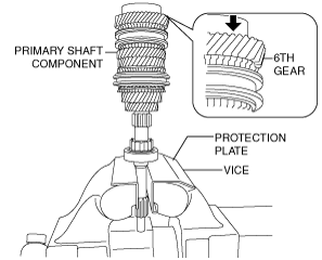
6th Gear Thrust Clearance Inspection (F66M-R)

1.  Secure the primary shaft component using a vice.

bf62zm00000023

Caution
•  Insert a protective plate between the vice and the part so as not to damage the part.

2.  Set the dial gauge to the position of the arrow shown in the figure.

bf62zm00000027

3.  Move the 6th gear in the axial direction and measure the 6th gear thrust clearance.

•  If it exceeds the maximum, inspect the 6th gear and surrounding parts for damage and wear and replace the malfunctioning part.
6th gear thrust clearance
Specification: 0.342 mm {0.0135 in}
Maximum: 0.461 mm {0.0181 in}