 |
bf62zm00000028
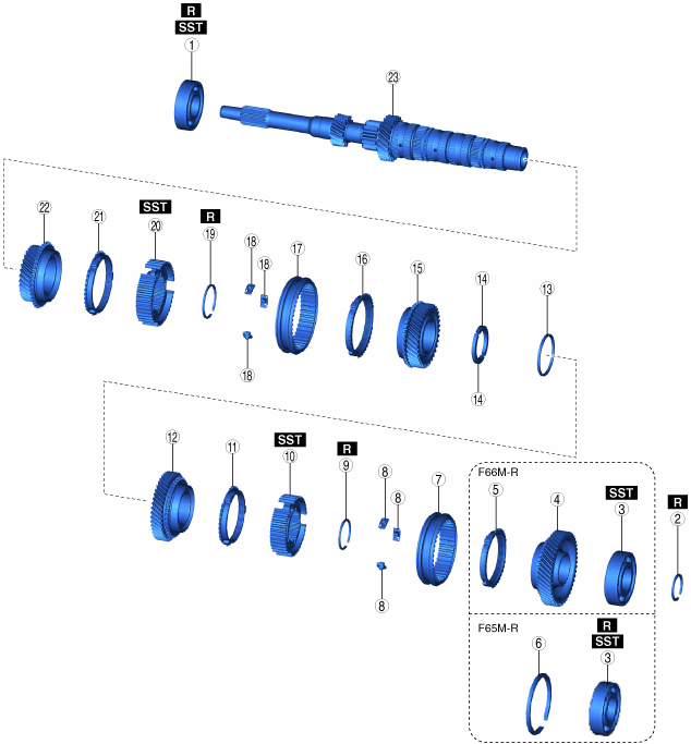
PRIMARY SHAFT COMPONENT DISASSEMBLY
id051500168700
1. Disassemble the primary shaft component in the order shown in the figure.
bf62zm00000028
|
|
1
|
Ball bearing
|
|
2
|
Clip
|
|
3
|
Ball bearing
|
|
4
|
6th gear
|
|
5
|
Synchronizer ring
|
|
6
|
Clip
|
|
7
|
Clutch hub sleeve
|
|
8
|
Synchronizer key
|
|
9
|
Clip
|
|
10
|
Clutch hub (5GR/6GR)
|
|
11
|
Synchronizer ring
|
|
12
|
5th gear
|
|
13
|
Holder
|
|
14
|
Thrust washer
|
|
15
|
4th gear
|
|
16
|
Synchronizer ring
|
|
17
|
Clutch hub sleeve
|
|
18
|
Synchronizer key
|
|
19
|
Clip
|
|
20
|
Clutch hub (3GR/4GR)
|
|
21
|
Synchronizer ring
|
|
22
|
3rd gear
|
|
23
|
Primary shaft
|
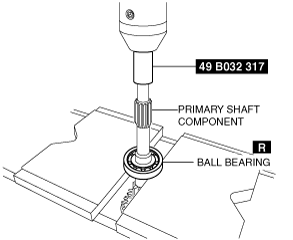
Ball Bearing (Clutch Housing Side) Removal Note
1. Set the primary shaft component and the SST in the press as shown in the figure.
bf62zm00000029
|
2. Remove the ball bearing using the press.
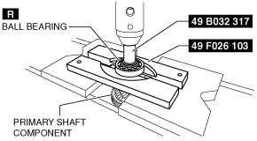
Ball Bearing (Transaxle Case Side) Removal Note
1. Set the SSTs and primary shaft component in the press as shown in the figure.
F65M-R
bf62zm00000030
|
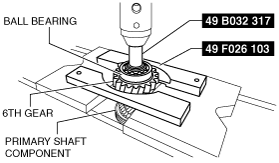
F66M-R
bf62zm00000031
|
2. Remove the ball bearing using the press. (F65M-R)
3. Remove the ball bearing and 6th gear using the press. (F66M-R)
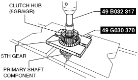
Clutch Hub (5GR/6GR) Removal Note
1. Set the SSTs and primary shaft component in the press as shown in the figure.
bf62zm00000032
|
2. Remove the clutch hub (5GR/6GR), synchronizer ring and 5th gear as a single unit using the press.
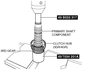
Clutch Hub (3GR/4GR) Removal Note
1. Set the SST and primary shaft component in the press as shown in the figure.
bf62zm00000033
|
2. Remove the clutch hub (3GR/4GR), synchronizer ring and 3rd gear as a single unit using the press.