DIFFERENTIAL BACKLASH ADJUSTMENT
id051500169400
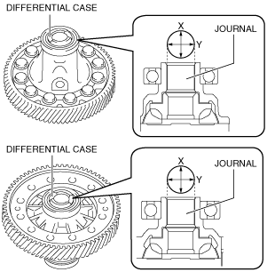
1. Measure the inner diameter of the differential case journal in the X and Y directions as shown in the figure.
-
Inner diameter of differential case journal
-
Specification: 28.020—28.059 mm {1.1032—1.1046 in}
-
• If not within the specification, replace the differential case.
2. Measure the outer diameter of the drive shaft journal in the X and Y directions as shown in the figure.
-
Outer diameter of drive shaft journal
-
LH minimum: 27.959 mm {1.1007 in}
RH minimum: 27.944 mm {1.1002 in}
-
• If not within the minimum specification, repair or replace.
-
Note
-
• For the drive shaft disassembly/assembly procedure, verify the workshop manual.
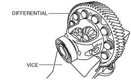
3. Secure the differential in a vice.
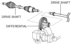
4. Assemble the drive shaft to the differential.
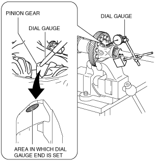
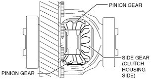
5. Set the dial gauge with the measuring probe attached perpendicularly to the area shown in the figure for the pinion gear.
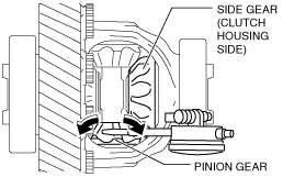
6. Measure the side gear on the clutch housing side and the pinion gear backlash using the following procedure:
- (1) Secure the side gear on the clutch housing side by hand.
- (2) Measure the backlash by moving the pinion gear with the dial gauge that has been set and determine measured value A.
-
-
Caution
-
• Because a difference occurs in the backlash measurement value if the secured side gear moves, move the pinion gear by hand so that the secured side gear does not move.
- (3) Measure the backlash of the opposite pinion gear in the same way as in Step 6 (2) and determine measured value B.
-
- (4) Calculate the average value of measured values A and B using the following formula and determine the backlash measurement value on the clutch housing side of the pinion gear.
-
-
• (Measured value A + measured value B) /2 = Backlash measurement value on clutch housing side
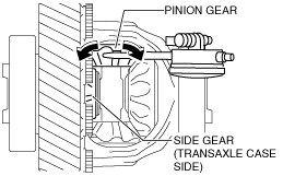
7. Measure the side gear on the transaxle case side and the pinion gear backlash using the following procedure:
- (1) Secure the side gear on the transaxle case side by hand.
- (2) Measure the backlash by moving the pinion gear to which the dial gauge has been set and determine measured value C.
-
-
Caution
-
• Because a difference occurs in the backlash measurement value if the secured side gear moves, move the pinion gear by hand so that the secured side gear does not move.
- (3) Measure the backlash of the opposite pinion gear in the same way as in Step 7 (2) and determine measured value D.
-
- (4) Calculate the average value of measured values C and D using the following formula and determine the backlash measurement value on the transaxle case side of the pinion gear.
-
-
• (Measured value C + measured value D) /2 = Backlash measurement value on transaxle case side
8. Verify that the backlash on each side is within the specification.
-
Differential pinion gear backlash
-
Specification: 0.03—0.15 mm {0.002—0.005 in}
-
• If the measured backlash value on each side is within the specification, there is no problem because the thrust washer thickness is the same as the removed one and, therefore, the differential preload adjustment procedure is finished.
• If the thrust washer thickness exceeds the specification even though 0.95 mm {0.037 in} is used, replace the differential case.
Thrust Washer Selection Calculation
-
Note
-
• Perform the thrust washer selection calculation on each side.
1. Calculate the backlash gap by subtracting constant number A from the backlash measurement value.
-
• Constant number A =0.060 mm {0.0024 in}
• Measured backlash value - 0.060 mm {0.0024 in}= Backlash gap
-
Calculation example
-
• Measured backlash value =0.165 mm {0.00650 in}
• 0.165 mm {0.00650 in} - 0.060 mm {0.0024 in}=0.105 mm {0.00413 in}
2. Calculate the thrust washer thickness gap by multiplying the backlash gap by constant number B.
-
Calculation method [mm]
-
• Constant number B =1.25
• Backlash gap x 1.25= Thrust washer thickness gap
Calculation example
-
• Backlash gap =0.105 mm
• 0.105 mm x 1.25=0.13125 mm
-
Calculation method [in]
-
• Constant number B =1.3
• Backlash gap x 1.3= Thrust washer thickness gap
Calculation example
-
• Backlash gap =0.00413 in
• 0.00413 in x 1.3=0.005369 in
3. Calculate the thrust washer thickness calculated value by adding the thrust washer thickness gap to the thickness of the thrust washer used in the measurement.
-
• Thickness of thrust washer used in measurement + thrust washer thickness gap = Thrust washer thickness calculated value
-
Calculation example
-
• Thickness of thrust washer used in measurement =0.810 mm {0.0319 in}
• Thrust washer thickness gap =0.13125 mm {0.005369 in}
• 0.810 mm {0.0319 in}+0.13125 mm {0.005369 in}=0.94125 mm {0.037269 in}
4. Calculate the thickness of the thrust washer on the opposite side the same way.
5. Compare the calculated thickness value of each thrust washer with the following table and select a thrust washer of the appropriate thickness.
-
Caution
-
• Select a thrust washer of the same thickness for each side. However, if the measurement value cannot be adjusted within the specification, select different thicknesses for the thrust washers.
|
Calculated value of thrust washer thickness
|
Appropriate thrust washer thickness (mm {in})
|
|
Calculated thrust washer thickness value or more (mm {in})
|
Less than calculated value of thrust washer thickness (mm {in})
|
|
0.925 {0.0364}
|
1.025 {0.04035}
|
0.95 {0.037}
|
|
0.875 {0.0344}
|
0.925 {0.0364}
|
0.90 {0.035}
|
|
0.825 {0.0325}
|
0.875 {0.0344}
|
0.85 {0.033}
|
|
0.775 {0.0305}
|
0.825 {0.0325}
|
0.80 {0.031}
|
|
0.675 {0.0266}
|
0.775 {0.0305}
|
0.75 {0.030}
|
Selection example
• For a calculated thrust washer thickness value of 0.94125 mm {0.037269 in}, a thrust washer with a thickness of 0.95 mm {0.037 in} is selected because the calculated thrust washer thickness value is 0.925 mm {0.0364 in} or more and less than 1.025 mm {0.04035 in}.
-
Note
-
• Constant number A, 0.060 mm {0.0024 in} is the backlash median value of the specification.
• The backlash gap is the difference between the backlash median value of the specification and the backlash measurement value.
• Constant number B is the thrust washer thickness which varies each time the backlash changes by 1.0 mm {0.039 in}. When the backlash is changed 0.08 mm {0.003 in}, the quotient becomes 1.25 mm/mm {1.3 in/in} because the thrust washer thickness has changed 0.1 mm {0.004 in}.
• The thrust washer thickness gap is the difference between the thickness of the thrust washer used in the measurement and the thickness of an appropriate thrust washer. In the formula to calculate the thrust washer thickness gap, the thrust washer thickness gap is calculated by multiplying the backlash gap with constant number B.