SHIM ADJUSTMENT
id051500285000
Primary Shaft Shim Adjustment
1. Measure the thickness of the straight edge which is used for measurements.
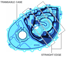
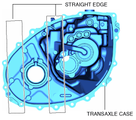
2. Measure distance A of the transaxle case using the following procedure.
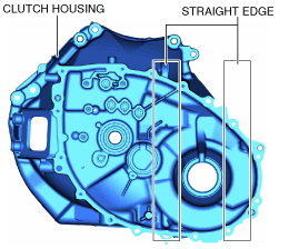
- (1) Place two straight edges on the transaxle case as shown in the figure.
-
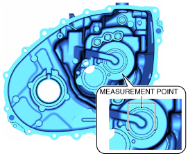
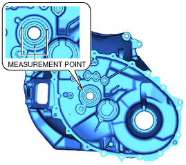
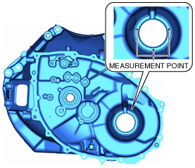
- (2) Set up 3 measurement points of your choosing on the shim assembly area of the clutch housing as shown in the figure.
-
- (3) Using a commercially available depth gauge, measure the distance to each measurement point from the straight edge.
-
-
Caution
-
• When measuring the distance to the measurement point from the straight edge, do not allow the depth gauge head to contact the shim assembly area.
- (4) Calculate the average value measured in Step 3 using the following formula.
-
-
• (Value of first measurement + 2 value of second measurement + 3 value of third measurement) / 3 = Average measured values.
-
Calculation example
-
• First measured value =232.069 mm {9.13658 in}
• Second measured value =232.071 mm {9.13666 in}
• Third measured value =232.070 mm {9.13662 in}
• (232.069 mm {9.13658 in}+232.071 mm {9.13666 in}+232.070 mm {9.13662 in}) / 3 = 232.070 mm {9.13662 in}
- (5) Calculate distance A of the transaxle case using the following formula.
-
-
• Average of measured values - straight edge thickness = Distance A
-
Calculation example
-
• Straight edge thickness =5.000 mm {0.1969 in}
• Measured average value =232.070 mm {9.13662 in}
• 232.070 mm {9.13662 in} - 5.000 mm {0.1969 in}=227.070 mm {8.93977 in}
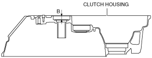
3. Measure distance B of the transaxle case using the following procedure.
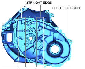
- (1) Set two straight edges on the clutch housing as shown in the figure.
-
- (2) Set up 3 measurement points of your choosing on the ball bearing assembly area of the clutch housing as shown in the figure.
-
- (3) Using a commercially available depth gauge, measure the distance to each measurement point from the straight edge.
-
-
Caution
-
• When measuring the distance to the measurement points from the straight edge, do not allow the depth gauge head to contact the ball bearing assembly area.
- (4) Calculate the average value measured in Step 3 using the following formula.
-
-
• (Value of first measurement + 2 value of second measurement + 3 value of third measurement) / 3 = Average measured values.
-
Calculation example
-
• First measured value =19.001 mm {0.74807 in}
• Second measured value =18.999 mm {0.74799 in}
• Third measured value =19.000 mm {0.74803 in}
• (19.001 mm {0.74807 in}+18.999 mm {0.74799 in}+19.000 mm {0.74803 in}) / 3 = 19.000 mm {0.74803 in}
- (5) Calculate distance B of the clutch housing using the following formula.
-
-
• Average of measured values - straight edge thickness = Distance B
-
Calculation example
-
• Straight edge thickness =5.000 mm {0.1969 in}
• Measured average value =19.000 mm {0.74803 in}
• 19.000 mm {0.74803 in} - 5.000 mm {0.1969 in}=14.000 mm {0.55118 in}
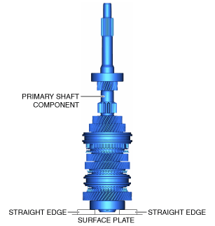
4. Measure distance C of the primary shaft component using the following procedure.
- (1) Place two straight edges on the surface plate as shown in the figure and set the primary shaft component on top of them.
-
-
Caution
-
• To measure distance C correctly, set the primary shaft component so that the straight edge does not contact the ball bearing inner race.
- (2) Set up 3 measurement points of your choosing on the ball bearing as shown in the figure.
-
- (3) Using a commercially available height gauge, measure the distance to each measurement point from the straight edge.
- (4) Calculate the average of the value measured in Step 3 using the following formula, and use the average of the measured value for distance C of the primary shaft component.
-
-
• (Value of first measurement + value of second measurement + value of third measurement) / 3 = Distance C
-
Calculation example
-
• First measured value =239.706 mm {9.43725 in}
• Second measured value =239.705 mm {9.43721 in}
• Third measured value =239.707 mm {9.43729 in}
• (239.706 mm {9.43725 in}+239.705 mm {9.43721 in}+239.707 mm {9.43729 in}) / 3 =239.706 mm {9.43725 in}
5. Select the primary shaft shim using the following procedure.
- (1) Calculate the clearance (clearance D) between the transaxle case and the primary shaft component using the following formula.
-
-
• Distance A + Distance B - Distance C = Clearance D
-
Calculation example
-
• Distance A =227.070 mm {8.93977 in}
• Distance B =14.000 mm {0.55118 in}
• Distance C =239.706 mm {9.43725 in}
• 227.070 mm {8.93977 in}+14.000 mm {0.55118 in} - 239.706 mm {9.43725 in}=1.364 mm {0.05370 in}
- (2) Compare the calculated value for clearance D with the following table and select a shim of the appropriate thickness.
-
|
Clearance D measured value
|
Appropriate shim thickness (mm {in})
|
|
Calculated shim thickness of more (mm {in})
|
Less than calculated shim thickness (mm {in})
|
|
1.570 {0.06181}
|
1.610 {0.06339}
|
1.550 {0.06102}
|
|
1.520 {0.05984}
|
1.570 {0.06181}
|
1.500 {0.05906}
|
|
1.470 {0.05787}
|
1.520 {0.05984}
|
1.450 {0.05709}
|
|
1.420 {0.05591}
|
1.470 {0.05787}
|
1.400 {0.05512}
|
|
1.370 {0.05394}
|
1.420 {0.05591}
|
1.350 {0.05315}
|
|
1.320 {0.05197}
|
1.370 {0.05394}
|
1.300 {0.05118}
|
|
1.270 {0.05000}
|
1.320 {0.05197}
|
1.250 {0.04921}
|
|
1.220 {0.04803}
|
1.270 {0.05000}
|
1.200 {0.04724}
|
|
1.170 {0.04606}
|
1.220 {0.04803}
|
1.150 {0.04528}
|
|
1.120 {0.04409}
|
1.170 {0.04606}
|
1.100 {0.04331}
|
|
1.070 {0.04213}
|
1.120 {0.04409}
|
1.050 {0.04134}
|
|
1.020 {0.04016}
|
1.070 {0.04213}
|
1.000 {0.03937}
|
|
0.970 {0.03819}
|
1.020 {0.04016}
|
0.950 {0.03740}
|
|
0.920 {0.03622}
|
0.970 {0.03819}
|
0.900 {0.03543}
|
|
0.870 {0.03425}
|
0.920 {0.03622}
|
0.850 {0.03346}
|
|
0.820 {0.03228}
|
0.870 {0.03425}
|
0.800 {0.03150}
|
|
0.770 {0.03031}
|
0.820 {0.03228}
|
0.750 {0.02953}
|
|
0.720 {0.02835}
|
0.770 {0.03031}
|
0.700 {0.02756}
|
|
0.670 {0.02638}
|
0.720 {0.02835}
|
0.650 {0.02559}
|
|
0.620 {0.02441}
|
0.670 {0.02638}
|
0.600 {0.02362}
|
Selection example
• For clearance D 1.364 mm {0.05370 in}, select a shim with a thickness of 1.300 mm {0.05118 in} because the calculated shim thickness value is 1.320 mm {0.05197 in} or more and less than 1.370 mm {0.05394 in}.
Differential Shim Adjustment
1. Measure the thickness of the straight edge which is used for measurements.
2. Measure distance E of the transaxle case using the following procedure.
- (1) Place two straight edges on the transaxle case as shown in the figure.
-
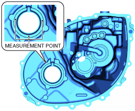
- (2) Set up 3 measurement points of your choosing on the shim assembly area of the transaxle case as shown in the figure.
-
- (3) Using a commercially available depth gauge, measure the distance to each measurement point from the straight edge.
-
-
Caution
-
• When measuring the distance to the measurement point from the straight edge, do not allow the depth gauge head to contact the shim assembly area.
- (4) Calculate the average value measured in Step 3 using the following formula.
-
-
• (Value of first measurement + 2 value of second measurement + 3 value of third measurement) / 3 = Average measured values.
-
Calculation example
-
• First measured value =25.901 mm {1.0197 in}
• Second measured value =25.899 mm {1.0196 in}
• Third measured value =25.900 mm {1.0197 in}
• (25.901 mm {1.0197 in}+25.899 mm {1.0196 in}+25.900 mm {1.0197 in}) / 3 =25.900 mm {1.0197 in}
- (5) Calculate distance E of the transaxle case using the following formula.
-
-
• Average of measured values - straight edge thickness = Distance E
-
Calculation example
-
• Straight edge thickness =5.000 mm {0.1969 in}
• Measured average value =25.900 mm {1.0197 in}
• 25.900 mm {1.0197 in} - 5.000 mm {0.1969 in}=20.900 mm {0.82284 in}
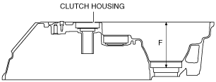
3. Measure distance F of the transaxle case using the following procedure.
- (1) Set two straight edges on the clutch housing as shown in the figure.
-
- (2) Set up 3 measurement points of your choosing on the ball bearing assembly area of the clutch housing as shown in the figure.
-
- (3) Using a commercially available depth gauge, measure the distance to each measurement point from the straight edge.
-
-
Caution
-
• When measuring the distance to the measurement point from the straight edge, do not allow the depth gauge head to contact the bearing outer race assembly area.
- (4) Calculate the average value measured in Step 3 using the following formula.
-
-
• (Value of first measurement + 2 value of second measurement + 3 value of third measurement) / 3 = Average measured values.
-
Calculation example
-
• First measured value =106.099 mm {4.17713 in}
• Second measured value =106.100 mm {4.17717 in}
• Third measured value =106.101 mm {4.17721 in}
• (106.099 mm {4.17713 in}+106.100 mm {4.17717 in}+106.101 mm {4.17721 in}) / 3 =106.100 mm {4.17717 in}
- (5) Calculate distance F of the clutch housing using the following formula.
-
-
• Average of measured values - straight edge thickness = Distance F
-
Calculation example
-
• Straight edge thickness =5.000 mm {0.1969 in}
• Measured average value =106.100 mm {4.17717 in}
• 106.100 mm {4.17717 in} - 5.000 mm {0.1969 in}=101.100 mm {3.98032 in}
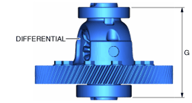
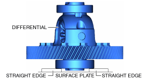
4. Measure distance G of the differential using the following procedure.
- (1) Place two straight edges on the surface plate as shown in the figure and set the differential on top of them.
-
-
Caution
-
• To measure distance G correctly, set the differential so that the straight edge does not contact the ball bearing inner race.
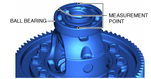
- (2) Set up 3 measurement points of your choosing on the ball bearing as shown in the figure.
-
- (3) Using a commercially available height gauge, measure the distance to each measurement point from the straight edge.
- (4) Calculate the average of the value measured in Step 4 using the following formula, and use the average of the measured value for distance G of the differential.
-
-
• (Value of first measurement + 2 value of second measurement + 3 value of third measurement) / 3 = Distance G
-
Calculation example
-
• First measured value =120.898 mm {4.75977 in}
• Second measured value =120.899 mm {4.75981 in}
• Third measured value =120.897 mm {4.75973 in}
• (120.898 mm {4.75977 in}+120.899 mm {4.75981 in}+120.897 mm {4.75973 in}) / 3 =120.898 mm {4.75977 in}
5. Select the differential shim using the following procedure.
- (1) Calculate the clearance (clearance H) between the transaxle case and the primary shaft component using the following formula.
-
-
• Distance E + Distance F - Distance G = Clearance H
-
Calculation example
-
• Distance E =20.900 mm {0.82284 in}
• Distance F =101.100 mm {3.98032 in}
• Distance G =120.898 mm {4.75977 in}
• 20.900 mm {0.82284 in}+101.100 mm {3.98032 in} - 120.898 mm {4.75977 in}=1.102 mm {0.04339 in}
- (2) Compare the calculated value for clearance H with the following table and select a shim of the appropriate thickness.
-
|
Clearance H measured value
|
Appropriate shim thickness (mm {in})
|
|
Calculated shim thickness of more (mm {in})
|
Less than calculated shim thickness (mm {in})
|
|
1.620 {0.06378}
|
1.670 {0.06575}
|
1.600 {0.06299}
|
|
1.570 {0.06181}
|
1.620 {0.06378}
|
1.550 {0.06102}
|
|
1.520 {0.05984}
|
1.570 {0.06181}
|
1.500 {0.05906}
|
|
1.470 {0.05787}
|
1.520 {0.05984}
|
1.450 {0.05709}
|
|
1.420 {0.05591}
|
1.470 {0.05787}
|
1.400 {0.05512}
|
|
1.370 {0.05394}
|
1.420 {0.05591}
|
1.350 {0.05315}
|
|
1.320 {0.05197}
|
1.370 {0.05394}
|
1.300 {0.05118}
|
|
1.270 {0.05000}
|
1.320 {0.05197}
|
1.250 {0.04921}
|
|
1.220 {0.04803}
|
1.270 {0.05000}
|
1.200 {0.04724}
|
|
1.170 {0.04606}
|
1.220 {0.04803}
|
1.150 {0.04528}
|
|
1.120 {0.04409}
|
1.170 {0.04606}
|
1.100 {0.04331}
|
|
1.070 {0.04213}
|
1.120 {0.04409}
|
1.050 {0.04134}
|
|
1.020 {0.04016}
|
1.070 {0.04213}
|
1.000 {0.03937}
|
|
0.970 {0.03819}
|
1.020 {0.04016}
|
0.950 {0.03740}
|
|
0.920 {0.03622}
|
0.970 {0.03819}
|
0.900 {0.03543}
|
|
0.870 {0.03425}
|
0.920 {0.03622}
|
0.850 {0.03346}
|
|
0.835 {0.03287}
|
0.870 {0.03425}
|
0.800 {0.03150}
|
Selection example
• For clearance H 1.102 mm {0.04339 in}, select a shim with a thickness of 1.050 mm {0.04134 in} because the calculated shim thickness value is 1.070 mm {0.04213 in} or more and less than 1.120 mm {0.04409 in}.