 |
am2zzw00014960
HYDRAULIC VARIABLE VALVE TIMING ACTUATOR INSPECTION [SKYACTIV-G 1.3, SKYACTIV-G 1.5]
id0110q3126800
Without Coolant Control Valve
1. Disconnect the negative battery cable. (See NEGATIVE BATTERY CABLE DISCONNECTION/CONNECTION.)
2. Remove the plug hole plate. (See PLUG HOLE PLATE REMOVAL/INSTALLATION [SKYACTIV-G 1.3, SKYACTIV-G 1.5].)
3. Remove the ignition coil/ion sensors. (See IGNITION COIL/ION SENSOR REMOVAL/INSTALLATION [SKYACTIV-G 1.3, SKYACTIV-G 1.5].)
4. Remove the cylinder head cover. (See TIMING CHAIN REMOVAL/INSTALLATION [SKYACTIV-G 1.3, SKYACTIV-G 1.5].)
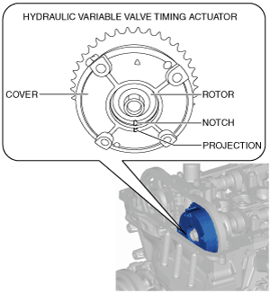
5. Verify the hydraulic variable valve timing actuator shape and identify the hydraulic variable valve timing actuator type.
am2zzw00014960
|
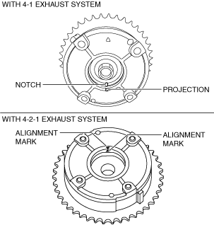
6. Inspect the hydraulic variable valve timing actuator. (See With 4-1 exhaust system.) (See With 4-2-1 exhaust system.)
7. Install in the reverse order of removal.
With 4-1 exhaust system
1. Verify that the notch of the rotor and projection of the cover on the hydraulic variable valve timing actuator are aligned and fitted.
am2zzw00011036
|
With 4-2-1 exhaust system
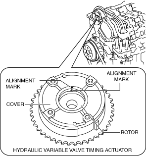
1. Verify that the alignment mark of the rotor and alignment mark of the cover on the hydraulic variable valve timing actuator are aligned and fitted.
am6xuw00008839
|
With Coolant Control Valve
1. Disconnect the negative battery cable. (See NEGATIVE BATTERY CABLE DISCONNECTION/CONNECTION.)
2. Remove the plug hole plate. (See PLUG HOLE PLATE REMOVAL/INSTALLATION [SKYACTIV-G 1.3, SKYACTIV-G 1.5].)
3. Remove the ignition coil/ion sensors. (See IGNITION COIL/ION SENSOR REMOVAL/INSTALLATION [SKYACTIV-G 1.3, SKYACTIV-G 1.5].)
4. Remove the cylinder head cover. (See TIMING CHAIN REMOVAL/INSTALLATION [SKYACTIV-G 1.3, SKYACTIV-G 1.5].)
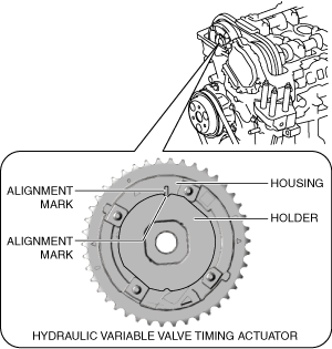
5. Verify that the alignment mark of the holder and alignment mark of the housing on the hydraulic variable valve timing actuator are aligned and fitted.
ac5uuw00009320
|
6. Install in the reverse order of removal.