ELECTRIC VARIABLE VALVE TIMING MOTOR/DRIVER REMOVAL/INSTALLATION [SKYACTIV-G 1.3, SKYACTIV-G 1.5]
id0110q3808100
Without coolant control valve (4-2-1 exhaust system), With coolant control valve
-
Warning
-
• A hot engine can cause severe burns. Turn off the engine and wait until it is cool before servicing.
-
Caution
-
• Applying excessive force (force of 100 N {10.2 kgf, 22.5 lbf} or more) to the electric variable valve timing motor/driver may cause a malfunction. When servicing, be careful not to apply excessive force to the electric variable valve timing motor/driver using other parts or tools.
• Do not disassemble the electric variable valve timing motor/driver because it is a precision unit.
1. Disconnect the negative battery cable. (See NEGATIVE BATTERY CABLE DISCONNECTION/CONNECTION.)
2. Remove the plug hole plate. (See PLUG HOLE PLATE REMOVAL/INSTALLATION [SKYACTIV-G 1.3, SKYACTIV-G 1.5].)
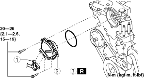
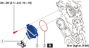
3. Remove in the order indicated in the table.
4. Install in the reverse order of removal.
Electric variable valve timing motor/driver type A
Electric variable valve timing motor/driver type B
|
1
|
Electric variable valve timing motor/driver connector
|
|
2
|
Electric variable valve timing motor/driver
|
|
3
|
O-ring
|
Electric Variable Valve Timing Motor/Driver Type A Installation Note
1. Install a new O-ring to the O-ring installation groove of the engine front cover.
-
Caution
-
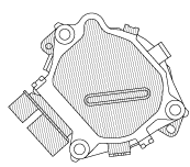
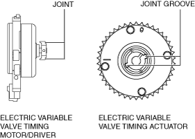
• To prevent damage to the electric variable valve timing motor/driver, do not apply excessive force (force of 100 N {10.2 kgf, 22.5 lbf} or more) to the shaded areas shown in the figure.
2. Install the electric variable valve timing motor/driver using the following procedures.
-
Note
-
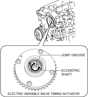
• The eccentric shaft on the electric variable valve timing actuator side can be rotated to the left and right.
• The electric variable valve timing motor/driver can be assembled with the joint groove of the eccentric shaft in any position, and it will not lead to vehicle damage or performance reduction.
- (1) Before installation, rotate the joint on the end of the electric variable valve timing motor so that it is aligned to the joint groove on the electric variable valve timing actuator side.
-
- (2) Engage the joint on the end of the electric variable valve timing motor with the joint groove on the electric variable valve timing actuator side.
-
- (3) Attach the seal surface.
-
- (4) Tighten the electric variable valve timing motor/driver installation bolts.
-
-
Tightening torque
-
20—26 N·m {2.1—2.6 kgf·m, 15—19 ft·lbf}
Electric Variable Valve Timing Motor/Driver Type B Installation Note
1. Install a new O-ring to the O-ring installation groove of the engine front cover.
-
Caution
-
• To prevent damage to the electric variable valve timing motor/driver, be careful not to perform the following.
-
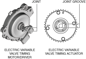
― Do not apply force of more than 100 N {10.2 kgf, 22.5 lbf} to the shaded area in figure and connector
― Do not deform areas (a) in figure
― Do not loosen areas (b) (crimp-tightened area) in figure
― Do not handle electric variable valve timing motor/driver while holding only connector
― Do not touch connector terminal
2. Install the electric variable valve timing motor/driver using the following procedures.
-
Note
-
• The eccentric shaft on the electric variable valve timing actuator side can be rotated to the left and right.
• The electric variable valve timing motor/driver can be assembled with the joint groove of the eccentric shaft in any position, and it will not lead to vehicle damage or performance reduction.
- (1) Before installation, rotate the joint on the end of the electric variable valve timing motor so that it is aligned to the joint groove on the electric variable valve timing actuator side.
-
- (2) Engage the joint on the end of the electric variable valve timing motor with the joint groove on the electric variable valve timing actuator side.
-
- (3) Attach the seal surface.
-
- (4) Tighten the electric variable valve timing motor/driver installation bolts.
-
-
Tightening torque
-
20—26 N·m {2.1—2.6 kgf·m, 15—19 ft·lbf}