 |
am2zzn00004907
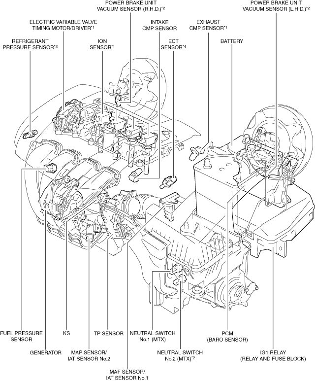
ENGINE CONTROL SYSTEM [SKYACTIV-G 1.3, SKYACTIV-G 1.5]
id0140q1139900
Outline
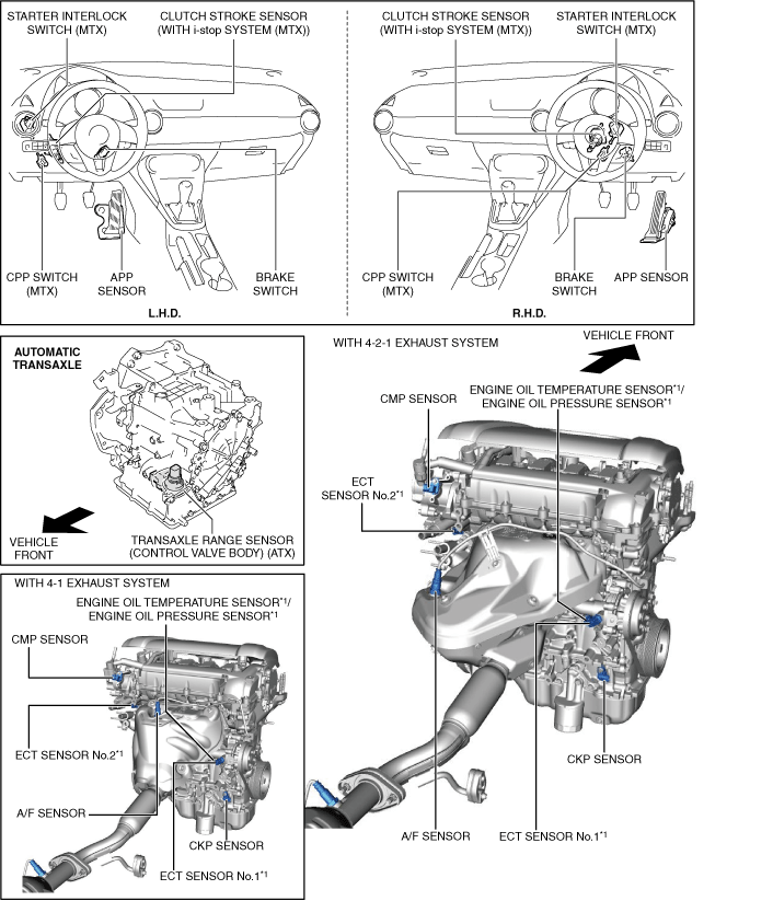
Structural View
Input device
am2zzn00004907
|
am2zzn00004996
|
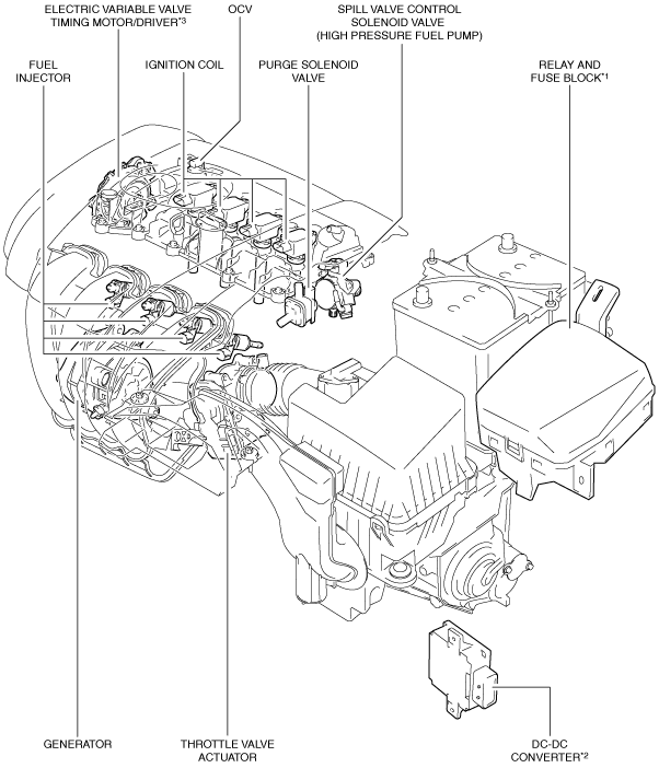
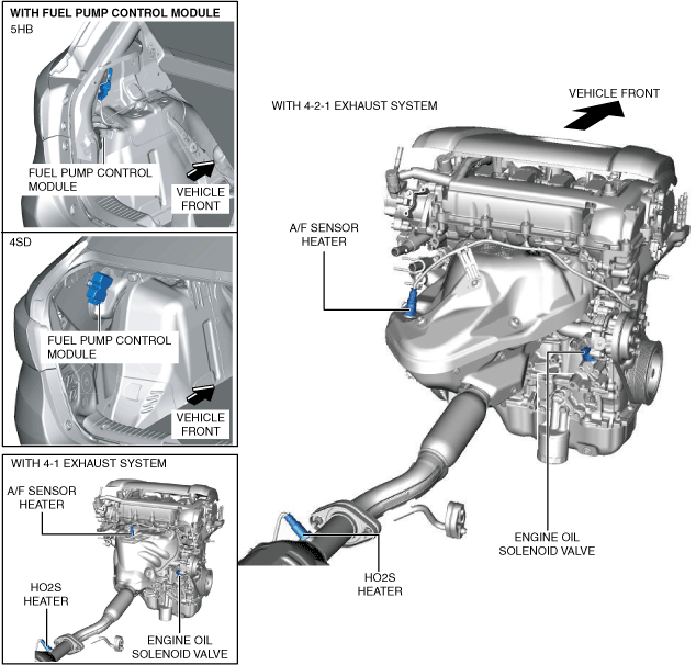
Output device
am2zzn00003570
|
am2zzn00004986
|
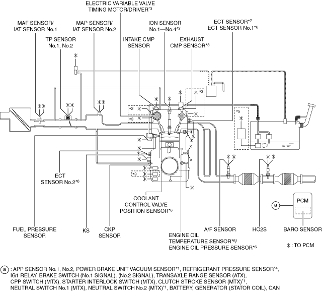
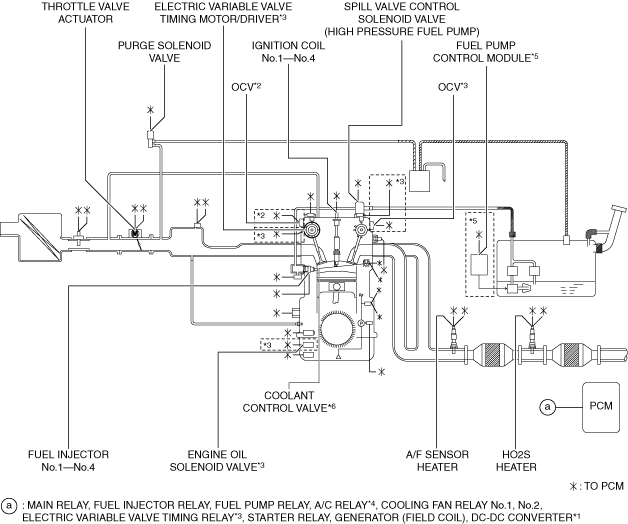
System Diagram
Input device
am2zzn00004913
|
Output device
am2zzn00004914
|
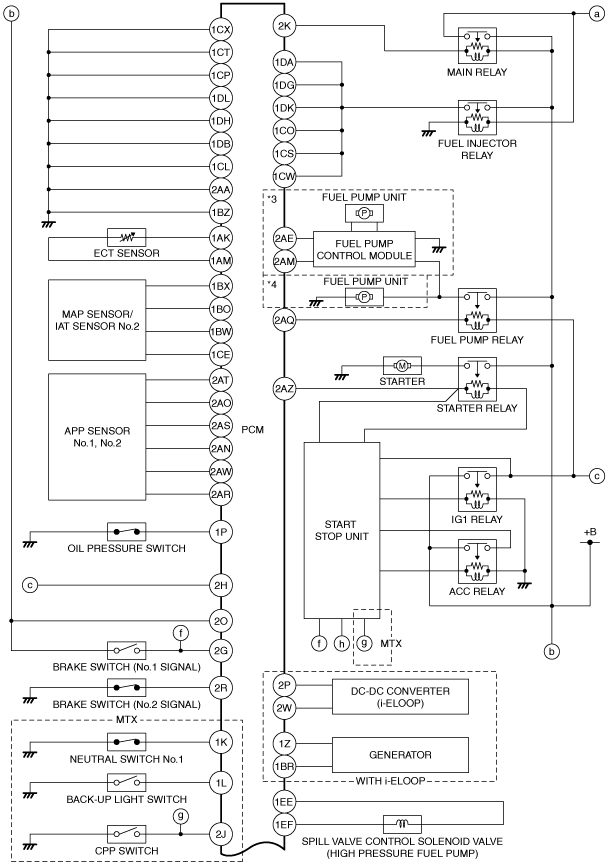
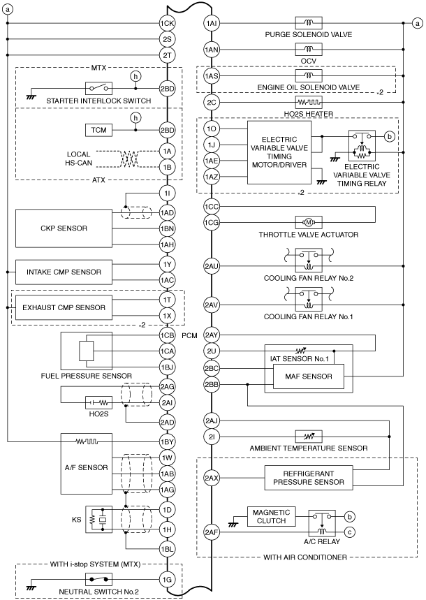
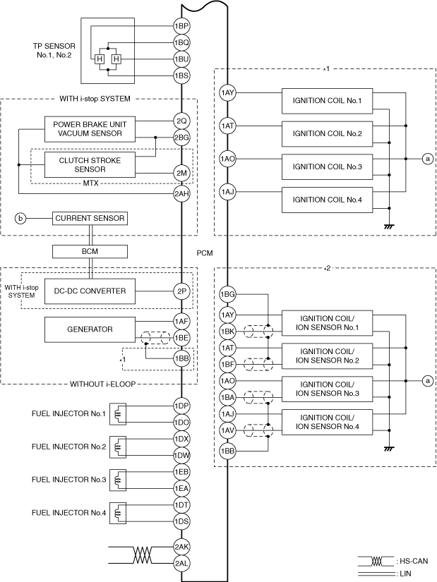
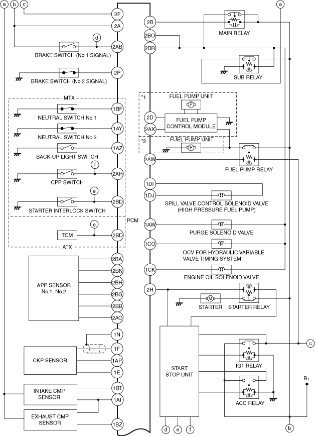
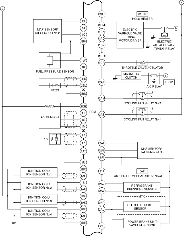
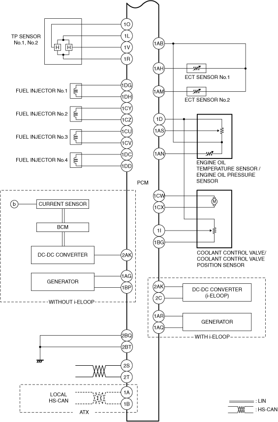
System Wiring Diagram
PCM (200 pin type)
am2zzw00012345
|
am2zzw00012346
|
am2zzw00014443
|
PCM (186 pin type)
am2zzw00015148
|
am2zzw00015149
|
am2zzw00015150
|
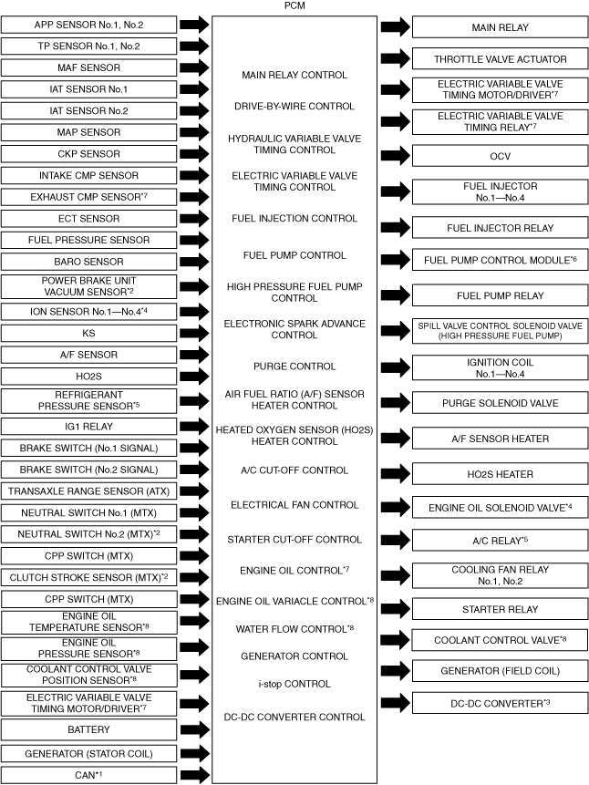
Block Diagram
am2zzn00005059
|
Relation Chart
|
Item |
 |
 |
 |
 |
 |
 |
 |
 |
 |
 |
 |
 |
 |
 |
 |
 |
 |
 |
 |
|---|---|---|---|---|---|---|---|---|---|---|---|---|---|---|---|---|---|---|---|
|
Input device
|
|||||||||||||||||||
|
APP sensor No.1, No.2
|
×
|
×
|
×
|
|
×
|
×
|
×
|
×
|
×
|
|
|
||||||||
|
TP sensor No.1, No.2
|
×
|
×
|
|
×
|
×
|
|
|
||||||||||||
|
MAF sensor
|
×
|
×
|
×
|
×
|
|
×
|
×
|
×
|
×
|
×
|
×
|
×
|
|
|
|||||
|
IAT sensor No.1
|
×
|
×
|
×
|
|
×
|
×
|
×
|
×*3
|
×
|
|
|
||||||||
|
IAT sensor No.2
|
×
|
×
|
×
|
|
×
|
×
|
|
|
|||||||||||
|
MAP sensor
|
×
|
×
|
×
|
|
×
|
×
|
×
|
×
|
|
|
|||||||||
|
CKP sensor
|
×
|
×
|
×
|
×
|
×
|
×
|
×
|
×
|
×
|
×
|
×
|
×
|
×
|
×
|
×
|
|
|
||
|
Intake CMP sensor
|
×
|
×
|
×
|
×
|
|
×
|
×
|
|
|
||||||||||
|
Exhaust CMP sensor*5
|
×
|
×
|
×
|
|
×
|
×
|
×
|
|
|
||||||||||
|
ECT sensor
|
×
|
×
|
×
|
×
|
|
×
|
×
|
×
|
×
|
×
|
×
|
×
|
×*3
|
×
|
×
|
|
|
||
|
Fuel pressure sensor
|
×
|
×
|
×
|
×
|
×
|
|
|
||||||||||||
|
BARO sensor
|
×
|
×
|
×
|
|
×
|
×
|
×
|
|
|
||||||||||
|
Power brake unit vacuum sensor*2
|
|
×
|
|
|
|||||||||||||||
|
Ion sensor No.1—No.4*6
|
×
|
×
|
|
|
|
||||||||||||||
|
KS
|
|
×
|
|
|
|||||||||||||||
|
A/F sensor
|
×
|
|
×
|
|
|
||||||||||||||
|
HO2S
|
×
|
|
|
|
|||||||||||||||
|
Refrigerant pressure sensor*6
|
|
×
|
×
|
|
|
||||||||||||||
|
IG1 relay
|
×
|
×
|
×
|
×
|
×
|
×
|
×
|
×
|
×
|
×
|
|
|
|||||||
|
Brake switch (No.1 signal)
|
×
|
|
×
|
|
|
||||||||||||||
|
Brake switch (No.2 signal)
|
×
|
|
|
|
|||||||||||||||
|
Transaxle range sensor (ATX)
|
×
|
×
|
|
×
|
×
|
|
|
||||||||||||
|
CPP switch (MTX)
|
×
|
×
|
|
×
|
×
|
×
|
|
|
|||||||||||
|
Starter interlock switch (MTX)
|
|
×
|
|
|
|||||||||||||||
|
Clutch stroke sensor (MTX)*2
|
|
×
|
|
|
|||||||||||||||
|
Neutral switch No.1 (MTX)
|
×
|
×
|
|
×
|
×
|
×
|
|
|
|||||||||||
|
Neutral switch No.2 (MTX)*2
|
|
×
|
|
|
|||||||||||||||
|
Electric variable valve timing motor/driver*5
|
×
|
|
×
|
|
|
||||||||||||||
|
Battery
|
×
|
×
|
×
|
×
|
×
|
×
|
×
|
|
|
||||||||||
|
Generator (Stator coil)
|
×
|
|
|
|
|||||||||||||||
|
Engine oil temperature sensor*8
|
|
×
|
×
|
×
|
|
|
|
|
|
|
|
|
|
|
|
|
|
×
|
×
|
|
Engine oil pressure sensor*8
|
|
|
|
|
|
|
|
|
|
|
|
|
|
|
|
|
|
×
|
|
|
Coolant control valve position sensor*8
|
|
|
|
|
|
|
|
|
|
|
|
|
|
|
|
|
|
|
×
|
|
CAN*1
|
×
|
×
|
|
×
|
×
|
×
|
×
|
×*2
|
×
|
×
|
|
|
|||||||
|
Output device
|
|||||||||||||||||||
|
Main relay
|
×
|
|
|
|
|||||||||||||||
|
Throttle valve actuator
|
×
|
|
×
|
|
|
||||||||||||||
|
Electric variable valve timing motor/driver*5
|
×
|
×
|
|
×
|
|
|
|||||||||||||
|
Electric variable valve timing relay*5
|
×
|
|
×
|
|
|
||||||||||||||
|
OCV
|
×
|
|
|
|
|||||||||||||||
|
Fuel injector No.1—No.4
|
×
|
|
×
|
|
|
||||||||||||||
|
Fuel injector relay
|
×
|
|
×
|
|
|
||||||||||||||
|
Fuel pump control module*7
|
×
|
|
|
||||||||||||||||
|
Fuel pump relay
|
×
|
|
|
||||||||||||||||
|
Spill valve control solenoid valve (High pressure fuel pump)
|
|
×
|
|
|
|||||||||||||||
|
Ignition coil No.1—No.4
|
|
×
|
×
|
|
|
||||||||||||||
|
Purge solenoid valve
|
|
×
|
|
|
|||||||||||||||
|
A/F sensor heater
|
|
×
|
|
|
|||||||||||||||
|
HO2S heater
|
|
×
|
|
|
|||||||||||||||
|
A/C relay*6
|
|
×
|
|
|
|||||||||||||||
|
Cooling fan relay No.1, No.2
|
|
×
|
|
|
|||||||||||||||
|
Starter relay
|
|
×
|
×
|
|
|
||||||||||||||
|
Generator (Field coil)
|
|
×
|
×
|
|
|
||||||||||||||
|
DC-DC converter*4
|
|
×
|
×
|
|
|
||||||||||||||
|
Engine oil solenoid valve*5
|
|
×
|
|
|
|||||||||||||||
|
Coolant control valve*8
|
|
|
|
|
|
|
|
|
|
|
|
|
|
|
|
|
|
|
×
|