GENERATOR CONTROL [SKYACTIV-G 1.3, SKYACTIV-G 1.5]
id0140q1208900
Outline
• Idling stability has been improved by optimum control of generator voltage (according to engine operation and electrical load conditions).
• The PCM determines the engine operation and electrical load conditions based on the input signals from each control part. It then uses this information to control the energization time of the generator field coils.
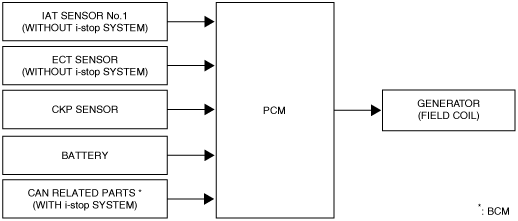
Block Diagram
Operation
Determination method for target excitation current
-
• The battery condition is determined based on the current sensor signal and the target excitation current is calculated according to the battery condition. If the current sensor is malfunctioning, the target excitation current is calculated from the generator target output amount (determined by battery fluid temperature, engine speed, and vehicle speed) and the actual generator rotation speed.
Determination method for field coil excitation time
-
• The PCM increases or decreases the field coil excitation current by sending a duty signal to the power transistor built into the generator.
• The field coil energization current changes according to changes in the power transistor excitation time. This is accomplished by changing the duty signal duty ratio. For example, when the battery positive voltage drops, the duty ratio of the duty signal sent to the power transistor is larger, increasing the field coil excitation current.
• During deceleration fuel-cut, the PCM increases the generator voltage and stores electricity in the battery. In conditions other than deceleration fuel-cut, only the required amount of electricity is charged (according to the battery status) to lower the load to the generator. (with i-stop system or i-ELOOP)