 |
am3zzw00013565
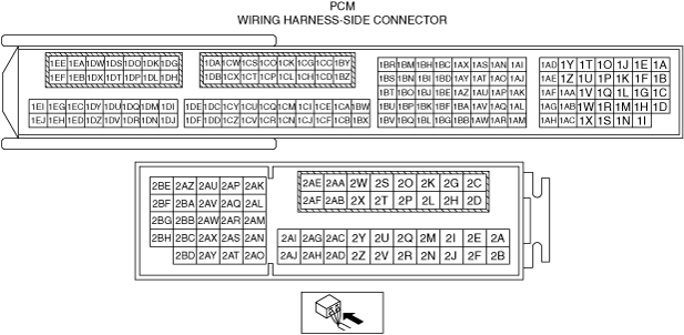
PCM INSPECTION [SKYACTIV-G 1.3, SKYACTIV-G 1.5]
id0140q1802500
Engine Type
|
Item |
Reference |
|
|---|---|---|
|
PCM (200 Pin Type)
|
Without Using the M-MDS
|
|
|
With Using the M-MDS
|
||
|
PCM (186 Pin Type)
|
Without Using the M-MDS
|
|
|
With Using the M-MDS
|
||
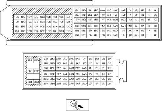
Without Using the M-MDS (PCM (200 Pin Type))
Terminal voltage table (Reference)
am3zzw00013565
|
|
Terminal |
Signal |
Connected to |
Test condition |
Voltage (V) |
Inspection item |
|
|---|---|---|---|---|---|---|
|
1A*1
|
CAN2_H
|
CAN system related modules
|
Because this terminal is for CAN, integrity determination by terminal voltage is not possible.
|
• Related wiring harness
|
||
|
1B*1
|
CAN2_L
|
CAN system related modules
|
Because this terminal is for CAN, integrity determination by terminal voltage is not possible.
|
• Related wiring harness
|
||
|
1C
|
—
|
—
|
—
|
—
|
—
|
|
|
1D
|
Knocking (–)
|
KS
|
Ignition switched ON (engine off) (Use digital type voltmeter, because measurement voltage will be detected less than true voltage when using analog type voltmeter)
|
Approx. 1.64
|
• KS
• Related wiring harness
|
|
|
1E
|
—
|
—
|
—
|
—
|
—
|
|
|
1F
|
—
|
—
|
—
|
—
|
—
|
|
|
1G*7
|
Neutral switch No.2
|
Neutral switch No.2
|
Switch ignition ON (engine off)
|
Neutral
|
Below 1.0
|
• Neutral switch No.2
• Related wiring harness
|
|
Except above
|
B+
|
|||||
|
1H
|
Knocking (+)
|
KS
|
Ignition switched ON (engine off) (Use digital type voltmeter, because measurement voltage will be detected less than true voltage when using analog type voltmeter)
|
Approx. 3.28
|
• KS
• Related wiring harness
|
|
|
1I
|
GND
|
Sensor shield
|
Under any condition
|
Below 1.0
|
• Related wiring harness
|
|
|
1J*5
|
Electric variable valve timing motor (rotation direction)
|
Electric variable valve timing motor/driver
|
• Electric variable valve timing motor/driver
• Related wiring harness
|
|||
|
1K*2
|
Neutral position
|
Neutral switch No.1
|
Shift lever is at neutral position
|
Below 1.0
|
• Neutral switch No.1
• Related wiring harness
|
|
|
Shift lever is not at neutral position
|
B+
|
|||||
|
1L*2
|
Back-up light
|
Back-up light switch
|
Shift lever is at R position
|
Below 1.0
|
• Back-up light switch
• Related wiring harness
|
|
|
Shift lever is not at R position
|
B+
|
|||||
|
1M
|
—
|
—
|
—
|
—
|
—
|
|
|
1N
|
—
|
—
|
—
|
—
|
—
|
|
|
1O*5
|
Electric variable valve timing motor (rotation pulse)
|
Electric variable valve timing motor/driver
|
• Electric variable valve timing motor/driver
• Related wiring harness
|
|||
|
1P
|
Oil pressure
|
Oil pressure switch
|
Ignition switched ON (engine off)
|
Below 1.0
|
• Oil pressure switch
• Related wiring harness
|
|
|
Idle (after warm up)
|
B+
|
|||||
|
1Q
|
—
|
—
|
—
|
—
|
—
|
|
|
1R
|
—
|
—
|
—
|
—
|
—
|
|
|
1S
|
—
|
—
|
—
|
—
|
—
|
|
|
1T*5
|
Exhaust CMP
|
Exhaust CMP sensor
|
(See Exhaust CMP signal.)
|
• Exhaust CMP sensor
• Related wiring harness
|
||
|
1U
|
—
|
—
|
—
|
—
|
—
|
|
|
1V
|
—
|
—
|
—
|
—
|
—
|
|
|
1W
|
A/F
|
A/F sensor
|
Idle (after warm up)
|
Approx. 4.18
|
• A/F sensor
• Related wiring harness
|
|
|
1X*5
|
GND
|
Exhaust CMP sensor
|
Under any condition
|
Below 1.0
|
• Related wiring harness
|
|
|
1Y
|
Intake CMP
|
Intake CMP sensor
|
(See Intake CMP signal.)
|
• Intake CMP sensor
• Related wiring harness
|
||
|
1Z*3
|
Generator output voltage
|
Generator
|
• Generator
• Related wiring harness
|
|||
|
1AA
|
—
|
—
|
—
|
—
|
—
|
|
|
1AB
|
A/F
|
A/F sensor
|
Idle (after warm up): 0 mA
|
• A/F sensor
• Related wiring harness
|
||
|
1AC
|
GND
|
Intake CMP sensor
|
Under any condition
|
Below 1.0
|
• Related wiring harness
|
|
|
1AD
|
CKP
|
CKP sensor
|
(See CKP signal.)
|
• CKP sensor
• Related wiring harness
|
||
|
1AE*5
|
Electric variable valve timing driver (diagnostic)
|
Electric variable valve timing motor/driver
|
• Electric variable valve timing motor/driver
• Related wiring harness
|
|||
|
1AF*4
|
Generator output voltage
|
Generator
|
• Generator
• Related wiring harness
|
|||
|
1AG
|
A/F
|
A/F sensor
|
Idle (after warm up)
|
Approx. 4.01
|
• A/F sensor
• Related wiring harness
|
|
|
1AH
|
GND
|
CKP sensor
|
Under any condition
|
Below 1.0
|
• Related wiring harness
|
|
|
1AI
|
Purge control
|
Purge solenoid valve
|
(See Purge control.)
|
• Purge solenoid valve
• Related wiring harness
|
||
|
1AJ
|
IGT4
|
Ignition coil No.4
|
• Ignition coil No.4
• Related wiring harness
|
|||
|
1AK
|
ECT
|
ECT sensor
|
Ignition switched ON (engine off)
|
ECT 20 °C
{68 °F}
|
Approx. 3.10
|
• ECT sensor
• Related wiring harness
|
|
ECT 40 °C
{104 °F}
|
Approx. 2.16
|
|||||
|
ECT 60 °C
{140 °F}
|
Approx. 1.40
|
|||||
|
ECT 80 °C
{176 °F}
|
Approx. 0.87
|
|||||
|
ECT 100 °C
{212 °F}
|
Approx. 0.54
|
|||||
|
1AL
|
—
|
—
|
—
|
—
|
—
|
|
|
1AM
|
GND
|
ECT sensor
|
Under any condition
|
Below 1.0
|
• Related wiring harness
|
|
|
1AN
|
Hydraulic variable valve timing control
|
OCV
|
• OCV
• Related wiring harness
|
|||
|
1AO
|
IGT3
|
Ignition coil No.3
|
• Ignition coil No.3
• Related wiring harness
|
|||
|
1AP
|
—
|
—
|
—
|
—
|
—
|
|
|
1AQ
|
—
|
—
|
—
|
—
|
—
|
|
|
1AR
|
—
|
—
|
—
|
—
|
—
|
|
|
1AS*5
|
Engine oil control
|
Engine oil solenoid valve
|
(See Engine oil control signal.)
|
• Engine oil solenoid valve
• Related wiring harness
|
||
|
1AT
|
IGT2
|
Ignition coil No.2
|
• Ignition coil No.2
• Related wiring harness
|
|||
|
1AU
|
—
|
—
|
—
|
—
|
—
|
|
|
1AV*5
|
Ion (No.4)
|
Ion sensor No.4
|
Idle (after warm up)
|
Approx. 4.48
|
• Ion sensor No.4
• Related wiring harness
|
|
|
1AW
|
—
|
—
|
—
|
—
|
—
|
|
|
1AX
|
—
|
—
|
—
|
—
|
—
|
|
|
1AY
|
IGT1
|
Ignition coil No.1
|
• Ignition coil No.1
• Related wiring harness
|
|||
|
1AZ*5
|
Electric variable valve timing control
|
Electric variable valve timing motor/driver
|
• Electric variable valve timing motor/driver
• Related wiring harness
|
|||
|
1BA*5
|
Ion (No.3)
|
Ion sensor No.3
|
Idle (after warm up)
|
Approx. 4.48
|
• Ion sensor No.3
• Related wiring harness
|
|
|
1BB
|
GND
|
Sensor shield
|
Under any condition
|
Below 1.0
|
• Related wiring harness
|
|
|
1BC
|
—
|
—
|
—
|
—
|
—
|
|
|
1BD
|
—
|
—
|
—
|
—
|
—
|
|
|
1BE*4
|
Generator field coil control
|
Generator
|
• Generator
• Related wiring harness
|
|||
|
1BF*5
|
Ion (No.2)
|
Ion sensor No.2
|
Idle (after warm up)
|
Approx. 4.48
|
• Ion sensor No.2
• Related wiring harness
|
|
|
1BG
|
GND
|
Sensor shield
|
Under any condition
|
Below 1.0
|
• Related wiring harness
|
|
|
1BH
|
—
|
—
|
—
|
—
|
—
|
|
|
1BI
|
—
|
—
|
—
|
—
|
—
|
|
|
1BJ
|
Constant voltage (Vref)
|
Fuel pressure sensor
|
Ignition switched ON (engine off)
|
Approx. 5.02
|
• Related wiring harness
|
|
|
1BK*5
|
Ion (No.1)
|
Ion sensor No.1
|
Idle (after warm up)
|
Approx. 4.48
|
• Ion sensor No.1
• Related wiring harness
|
|
|
1BL
|
GND
|
Sensor shield
|
Under any condition
|
Below 1.0
|
• Related wiring harness
|
|
|
1BM
|
—
|
—
|
—
|
—
|
—
|
|
|
1BN
|
Constant voltage (Vref)
|
CKP sensor
|
Ignition switched ON (engine off)
|
Approx. 5.02
|
• Related wiring harness
|
|
|
1BO
|
Constant voltage (Vref)
|
MAP sensor
|
Ignition switched ON (engine off)
|
Approx. 5.02
|
• Related wiring harness
|
|
|
1BP
|
TP (No.1)
|
TP sensor No.1
|
Ignition switched ON (engine off)
|
Accelerator pedal released
|
Approx. 1.15
|
• TP sensor No.1
• Related wiring harness
|
|
Accelerator pedal fully depressed
|
Approx. 4.63
|
|||||
|
1BQ
|
GND
|
TP sensor No.1, TP sensor No.2
|
Under any condition
|
Below 1.0
|
• Related wiring harness
|
|
|
1BR*3
|
Generator field coil control
|
Generator
|
• Generator
• Related wiring harness
|
|||
|
1BS
|
Constant voltage (Vref)
|
TP sensor No.1, TP sensor No.2
|
Ignition switched ON (engine off)
|
Approx. 5.02
|
• Related wiring harness
|
|
|
1BT
|
—
|
—
|
—
|
—
|
—
|
|
|
1BU
|
TP (No.2)
|
TP sensor No.2
|
Ignition switched ON (engine off)
|
Accelerator pedal released
|
Approx. 3.95
|
• TP sensor No.2
• Related wiring harness
|
|
Accelerator pedal fully depressed
|
Approx. 0.45
|
|||||
|
1BV
|
—
|
—
|
—
|
—
|
—
|
|
|
1BW
|
MAP
|
MAP sensor
|
Ignition switched ON (engine off)
|
Approx. 4.15
|
• MAP sensor
• Related wiring harness
|
|
|
Idle (after warm up)
|
Approx. 1.96
|
|||||
|
Racing
(Engine speed: 2,000 rpm)
|
Approx. 1.33
|
|||||
|
1BX
|
GND
|
MAP sensor, IAT sensor No.2
|
Under any condition
|
Below 1.0
|
• Related wiring harness
|
|
|
1BY
|
A/F sensor heater control
|
A/F sensor heater
|
• A/F sensor heater
• Related wiring harness
|
|||
|
1BZ
|
GND
|
GND
|
Under any condition
|
Below 1.0
|
• Related wiring harness
|
|
|
1CA
|
Fuel pressure
|
Fuel pressure sensor
|
Idle (ECT 80°C{176 °F})
|
Approx. 0.9
|
• Fuel pressure sensor
• Related wiring harness
|
|
|
1CB
|
GND
|
Fuel pressure sensor
|
Under any condition
|
Below 1.0
|
• Related wiring harness
|
|
|
1CC
|
Drive-by-wire control (–)
|
Throttle valve actuator
|
Idle (after warm up)
Because the drive-by-wire control (-) terminal value varies depending on the vehicle, examination using only the ICC terminal is not possible. When performing the inspection, perform it together with the ICG terminal.
• Type A
• Type B
|
• Throttle valve actuator
• Related wiring harness
|
||
|
1CD
|
—
|
—
|
—
|
—
|
—
|
|
|
1CE
|
IAT (No.2)
|
IAT sensor No.2
|
Ignition switched ON (engine off)
|
IAT 20 °C
{68 °F}
|
Approx. 3.57
|
• IAT sensor No.2
• Related wiring harness
|
|
IAT 40 °C
{104 °F}
|
Approx. 2.70
|
|||||
|
IAT 60 °C
{140 °F}
|
Approx. 1.87
|
|||||
|
1CF
|
—
|
—
|
—
|
—
|
—
|
|
|
1CG
|
Drive-by-wire control (+)
|
Throttle valve actuator
|
• Throttle valve actuator
• Related wiring harness
|
|||
|
1CH
|
—
|
—
|
—
|
—
|
—
|
|
|
1CI
|
—
|
—
|
—
|
—
|
—
|
|
|
1CJ
|
—
|
—
|
—
|
—
|
—
|
|
|
1CK
|
Battery voltage
|
Main relay
|
Ignition switched ON (engine off)
|
B+
|
• Main relay
• Related wiring harness
|
|
|
1CL
|
GND
|
GND
|
Under any condition
|
Below 1.0
|
• Related wiring harness
|
|
|
1CM
|
—
|
—
|
—
|
—
|
—
|
|
|
1CN
|
—
|
—
|
—
|
—
|
—
|
|
|
1CO
|
Battery voltage
|
Fuel injector relay
|
Ignition switched ON (engine off)
|
B+
|
• Fuel injector relay
• Related wiring harness
|
|
|
1CP
|
GND
|
GND
|
Under any condition
|
Below 1.0
|
• Related wiring harness
|
|
|
1CQ
|
—
|
—
|
—
|
—
|
—
|
|
|
1CR
|
—
|
—
|
—
|
—
|
—
|
|
|
1CS
|
Battery voltage
|
Fuel injector relay
|
Ignition switched ON (engine off)
|
B+
|
• Fuel injector relay
• Related wiring harness
|
|
|
1CT
|
GND
|
GND
|
Under any condition
|
Below 1.0
|
• Related wiring harness
|
|
|
1CU
|
—
|
—
|
—
|
—
|
—
|
|
|
1CV
|
—
|
—
|
—
|
—
|
—
|
|
|
1CW
|
Battery voltage
|
Fuel injector relay
|
Ignition switched ON (engine off)
|
B+
|
• Fuel injector relay
• Related wiring harness
|
|
|
1CX
|
GND
|
GND
|
Under any condition
|
Below 1.0
|
• Related wiring harness
|
|
|
1CY
|
—
|
—
|
—
|
—
|
—
|
|
|
1CZ
|
—
|
—
|
—
|
—
|
—
|
|
|
1DA
|
Battery voltage
|
Fuel injector relay
|
Ignition switched ON (engine off)
|
B+
|
• Fuel injector relay
• Related wiring harness
|
|
|
1DB
|
GND
|
GND
|
Under any condition
|
Below 1.0
|
• Related wiring harness
|
|
|
1DC
|
—
|
—
|
—
|
—
|
—
|
|
|
1DD
|
—
|
—
|
—
|
—
|
—
|
|
|
1DE
|
—
|
—
|
—
|
—
|
—
|
|
|
1DF
|
—
|
—
|
—
|
—
|
—
|
|
|
1DG
|
Battery voltage
|
Fuel injector relay
|
Ignition switched ON (engine off)
|
B+
|
• Fuel injector relay
• Related wiring harness
|
|
|
1DH
|
GND
|
GND
|
Under any condition
|
Below 1.0
|
• Related wiring harness
|
|
|
1DI
|
—
|
—
|
—
|
—
|
—
|
|
|
1DJ
|
—
|
—
|
—
|
—
|
—
|
|
|
1DK
|
Battery voltage
|
Fuel injector relay
|
Ignition switched ON (engine off)
|
B+
|
• Fuel injector relay
• Related wiring harness
|
|
|
1DL
|
GND
|
GND
|
Under any condition
|
Below 1.0
|
• Related wiring harness
|
|
|
1DM
|
—
|
—
|
—
|
—
|
—
|
|
|
1DN
|
—
|
—
|
—
|
—
|
—
|
|
|
1DO
|
Fuel injection control (–)
|
Fuel injector No.1
|
• Fuel injector No.1
• Related wiring harness
|
|||
|
1DP
|
Fuel injection control (+)
|
Fuel injector No.1
|
• Fuel injector No.1
• Related wiring harness
|
|||
|
1DQ
|
—
|
—
|
—
|
—
|
—
|
|
|
1DR
|
—
|
—
|
—
|
—
|
—
|
|
|
1DS
|
Fuel injection control (–)
|
Fuel injector No.4
|
• Fuel injector No.4
• Related wiring harness
|
|||
|
1DT
|
Fuel injection control (+)
|
Fuel injector No.4
|
• Fuel injector No.4
• Related wiring harness
|
|||
|
1DU
|
—
|
—
|
—
|
—
|
—
|
|
|
1DV
|
—
|
—
|
—
|
—
|
—
|
|
|
1DW
|
Fuel injection control (–)
|
Fuel injector No.2
|
• Fuel injector No.2
• Related wiring harness
|
|||
|
1DX
|
Fuel injection control (+)
|
Fuel injector No.2
|
• Fuel injector No.2
• Related wiring harness
|
|||
|
1DY
|
—
|
—
|
—
|
—
|
—
|
|
|
1DZ
|
—
|
—
|
—
|
—
|
—
|
|
|
1EA
|
Fuel injection control (–)
|
Fuel injector No.3
|
• Fuel injector No.3
• Related wiring harness
|
|||
|
1EB
|
Fuel injection control (+)
|
Fuel injector No.3
|
• Fuel injector No.3
• Related wiring harness
|
|||
|
1EC
|
—
|
—
|
—
|
—
|
—
|
|
|
1ED
|
—
|
—
|
—
|
—
|
—
|
|
|
1EE
|
High pressure fuel pump control (+)
|
High pressure fuel pump
|
• High pressure fuel pump
• Related wiring harness
|
|||
|
1EF
|
High pressure fuel pump control (–)
|
High pressure fuel pump
|
• High pressure fuel pump
• Related wiring harness
|
|||
|
1EG
|
—
|
—
|
—
|
—
|
—
|
|
|
1EH
|
—
|
—
|
—
|
—
|
—
|
|
|
1EI
|
—
|
—
|
—
|
—
|
—
|
|
|
1EJ
|
—
|
—
|
—
|
—
|
—
|
|
|
2A
|
—
|
—
|
—
|
—
|
—
|
|
|
2B
|
—
|
—
|
—
|
—
|
—
|
|
|
2C
|
HO2S heater control
|
HO2S heater
|
(See HO2S heater control signal.)
|
• HO2S heater
• Related wiring harness
|
||
|
2D
|
—
|
—
|
—
|
—
|
—
|
|
|
2E
|
—
|
—
|
—
|
—
|
—
|
|
|
2F
|
—
|
—
|
—
|
—
|
—
|
|
|
2G
|
Brake (No.1)
|
Brake switch (No.1 signal)
|
Brake pedal released
|
Below 1.0
|
• Brake switch (No.1 signal)
• Related wiring harness
|
|
|
Brake pedal fully depressed
|
B+
|
|||||
|
2H
|
Ignition (IG1)
|
IG1 relay
|
Ignition switched ON (engine off)
|
B+
|
• IG1 relay
• Related wiring harness
|
|
|
2I
|
Ambient temperature
|
Ambient temperature sensor
|
Ignition switched ON (engine off)
|
AAT 20 °C
{68 °F}
|
Approx. 2.70
|
• Ambient temperature sensor
• Related wiring harness
|
|
AAT 30 °C
{104 °F}
|
Approx. 1.80
|
|||||
|
2J*2
|
CPP
|
CPP switch, start stop unit
|
Clutch pedal fully depressed
|
Below 1.0
|
• CPP switch
• Start stop unit
• Related wiring harness
|
|
|
Clutch pedal released
|
B+
|
|||||
|
2K
|
Main relay control
|
Main relay
|
Ignition switched ON (engine off)
|
Approx. 0.83
|
• Main relay
• Related wiring harness
|
|
|
2L
|
—
|
—
|
—
|
—
|
—
|
|
|
2M*7
|
Clutch stroke sensor
|
Clutch stroke sensor
|
Ignition switched ON (engine off)
|
Clutch pedal released
|
Approx. 4.56
|
• Clutch stroke sensor
• Related wiring harness
|
|
Clutch pedal fully depressed
|
Approx. 1.06
|
|||||
|
2N
|
—
|
—
|
—
|
—
|
—
|
|
|
2O
|
Battery voltage
|
Battery
|
Under any condition
|
B+
|
• Battery
• Related wiring harness
|
|
|
2P
|
DC-DC converter control*8
|
DC-DC converter
|
Ignition switched ON (engine off)
|
Below 1.0
|
• DC-DC converter
• Related wiring harness
|
|
|
DC-DC converter (i-ELOOP) control*3
|
DC-DC converter (i-ELOOP)
|
Ignition switched ON (engine off)
|
Below 1.0
|
• DC-DC converter (i-ELOOP)
• Related wiring harness
|
||
|
2Q*6
|
Power brake unit vacuum
|
Power brake unit vacuum sensor
|
Idle (after warm up)
|
Brake pedal released
|
Approx. 0.47
|
• Power brake unit vacuum sensor
• Related wiring harness
|
|
2R
|
Brake (No.2)
|
Brake switch (No.2 signal)
|
Brake pedal released
|
Below 1.0
|
• Brake switch (No.2 signal)
• Related wiring harness
|
|
|
Brake pedal fully depressed
|
B+
|
|||||
|
2S
|
Battery voltage
|
Main relay
|
Ignition switched ON (engine off)
|
B+
|
• Main relay
• Related wiring harness
|
|
|
2T
|
Battery voltage
|
Main relay
|
Ignition switched ON (engine off)
|
B+
|
• Main relay
• Related wiring harness
|
|
|
2U
|
IAT (No.1)
|
IAT sensor No.1
|
Ignition switched ON (engine off)
|
IAT 20 °C
{68 °F}
|
Approx. 2.64
|
• IAT sensor No.1
• Related wiring harness
|
|
IAT 40 °C
{104 °F}
|
Approx. 1.27
|
|||||
|
IAT 60 °C
{140 °F}
|
Approx. 0.66
|
|||||
|
2V
|
—
|
—
|
—
|
—
|
—
|
|
|
2W*3
|
DC-DC converter (i-ELOOP) control
|
DC-DC converter (i-ELOOP)
|
Idle (after warm up)
|
0 or B+
|
• DC-DC converter (i-ELOOP)
• Related wiring harness
|
|
|
2X
|
—
|
—
|
—
|
—
|
—
|
|
|
2Y
|
—
|
—
|
—
|
—
|
—
|
|
|
2Z
|
—
|
—
|
—
|
—
|
—
|
|
|
2AA
|
GND
|
GND
|
Under any condition
|
Below 1.0
|
• Related wiring harness
|
|
|
2AB
|
—
|
—
|
—
|
—
|
—
|
|
|
2AC
|
—
|
—
|
—
|
—
|
—
|
|
|
2AD
|
GND
|
Sensor shield
|
Under any condition
|
Below 1.0
|
• Related wiring harness
|
|
|
2AE*10
|
Fuel pump control
|
Fuel pump control module
|
(See Fuel pump control signal.)
|
• Fuel pump control module
• Related wiring harness
|
||
|
2AF*9
|
A/C cut-off control
|
A/C relay
|
A/C relay OFF
|
B+
|
• A/C relay
• Related wiring harness
|
|
|
A/C relay ON
|
Below 1.0
|
|||||
|
2AG
|
HO2S (–)
|
HO2S
|
Idle (after warm up)
|
Approx. 1.63
|
• HO2S
• Related wiring harness
|
|
|
2AH*6
|
GND
|
Power brake unit vacuum sensor, clutch stroke sensor*7
|
Under any condition
|
Below 1.0
|
• Related wiring harness
|
|
|
2AI
|
HO2S (+)
|
HO2S
|
Idle (after warm up)
|
Approx. 2.35
|
• HO2S
• Related wiring harness
|
|
|
2AJ
|
GND
|
Refrigerant pressure sensor, ambient temperature sensor
|
Under any condition
|
Below 1.0
|
• Related wiring harness
|
|
|
2AK
|
HS CAN_H
|
CAN system related modules
|
Because this terminal is for CAN, integrity determination by terminal voltage is not possible.
|
• Related wiring harness
|
||
|
2AL
|
HS CAN_L
|
CAN system related modules
|
Because this terminal is for CAN, integrity determination by terminal voltage is not possible.
|
• Related wiring harness
|
||
|
2AM*10
|
Fuel pump control (diagnostic)
|
Fuel pump control module
|
• Fuel pump control module
• Related wiring harness
|
|||
|
2AN
|
APP (No.1)
|
APP sensor No.1
|
Ignition switched ON (engine off)
|
Accelerator pedal released
|
Approx. 0.82
|
• APP sensor No.1
• Related wiring harness
|
|
Accelerator pedal fully depressed
|
Approx. 4.58
|
|||||
|
2AO
|
GND
|
APP sensor No.1
|
Under any condition
|
Below 1.0
|
• Related wiring harness
|
|
|
2AP
|
—
|
—
|
—
|
—
|
—
|
|
|
2AQ
|
Fuel pump control
|
Fuel pump relay
|
Ignition switched ON (engine off)
|
B+
|
• Fuel pump relay
• Related wiring harness
|
|
|
Idle (after warm up)
|
Below 1.0
|
|||||
|
2AR
|
Constant voltage (Vref)
|
APP sensor No.1
|
Ignition switched ON (engine off)
|
Approx. 5.02
|
• Related wiring harness
|
|
|
2AS
|
APP (No.2)
|
APP sensor No.2
|
Ignition switched ON (engine off)
|
Accelerator pedal released
|
Approx. 0.42
|
• APP sensor No.2
• Related wiring harness
|
|
Accelerator pedal fully depressed
|
Approx. 2.30
|
|||||
|
2AT
|
GND
|
APP sensor No.2
|
Under any condition
|
Below 1.0
|
• Related wiring harness
|
|
|
2AU
|
Cooling fan control
|
Cooling fan relay No.2
|
Cooling fan operating
|
Below 1.0
|
• Cooling fan relay No.2
• Related wiring harness
|
|
|
Cooling fan not operating
|
B+
|
|||||
|
2AV
|
Cooling fan control
|
Cooling fan relay No.1
|
Cooling fan operating
|
Below 1.0
|
• Cooling fan relay No.1
• Related wiring harness
|
|
|
Cooling fan not operating
|
B+
|
|||||
|
2AW
|
Constant voltage (Vref)
|
APP sensor No.2
|
Ignition switched ON (engine off)
|
Approx. 5.02
|
• Related wiring harness
|
|
|
2AX*9
|
Refrigerant pressure
|
Refrigerant pressure sensor
|
Refrigerant pressure: 1.0 MPa {10 kgf/cm2, 145 psi}
|
Approx. 1.58
|
• Refrigerant pressure sensor
• Related wiring harness
|
|
|
Refrigerant pressure: 1.1 MPa {11 kgf/cm2, 160 psi}
|
Approx. 1.72
|
|||||
|
Refrigerant pressure: 1.2 MPa {12 kgf/cm2, 174 psi}
|
Approx. 1.88
|
|||||
|
2AY
|
GND
|
MAF sensor, IAT sensor No.1
|
Under any condition
|
Below 1.0
|
• Related wiring harness
|
|
|
2AZ
|
Starter cut-off control
|
Starter relay, start stop unit
|
Ignition switched ON (engine off)
|
MTX
• Clutch pedal released
ATX
• Selector lever position is not P or N position
|
B+
|
• Starter relay
• Start stop unit
• Related wiring harness
|
|
MTX
• Clutch pedal fully depressed
ATX
• Selector lever position is P or N position
|
Below 1.0
|
|||||
|
2BA
|
—
|
—
|
—
|
—
|
—
|
|
|
2BB
|
Constant voltage (Vref)
|
Refrigerant pressure sensor*9, MAF sensor
|
Ignition switched ON (engine off)
|
Approx. 5.02
|
• Related wiring harness
|
|
|
2BC
|
MAF
|
MAF sensor
|
Ignition switched ON (engine off)
|
Approx. 0.76
|
• MAF sensor
• Related wiring harness
|
|
|
Idle (after warm up)
|
Approx. 1.12
|
|||||
|
Racing
(Engine speed: 2,000 rpm)
|
Approx. 1.44
|
|||||
|
2BD
|
Selector lever position*1
|
TCM, start stop unit
|
Selector lever position is not P or N position
|
B+
|
• TCM
• Start stop unit
• Related wiring harness
|
|
|
Selector lever position is P or N position
|
Below 1.0
|
|||||
|
Starter interlock*2
|
Starter interlock switch, start stop unit
|
Clutch pedal fully depressed
|
Below 1.0
|
• Starter interlock switch
• Start stop unit
• Related wiring harness
|
||
|
Clutch pedal released
|
B+
|
|||||
|
2BE
|
—
|
—
|
—
|
—
|
—
|
|
|
2BF
|
—
|
—
|
—
|
—
|
—
|
|
|
2BG*6
|
Constant voltage (Vref)
|
Power brake unit vacuum sensor, clutch stroke sensor*7
|
Switch ignition ON (engine off)
|
Approx. 5.02
|
• Related wiring harness
|
|
|
2BH
|
—
|
—
|
—
|
—
|
—
|
|
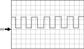
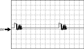
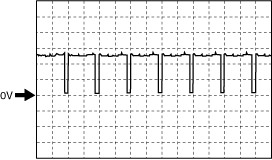
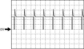
Inspection Using An Oscilloscope (Reference) (PCM (200 Pin Type))
Electric variable valve timing motor (rotation direction) signal
adejjw00007909
|
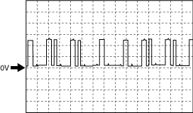
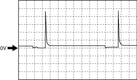
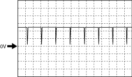
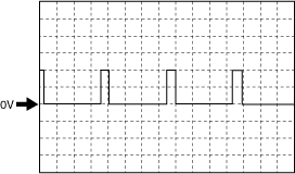
Electric variable valve timing motor (rotation pulse) signal
adejjw00007910
|
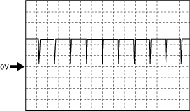
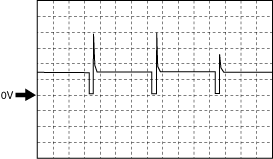
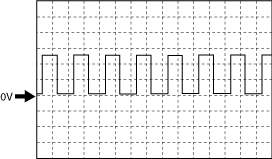
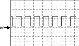
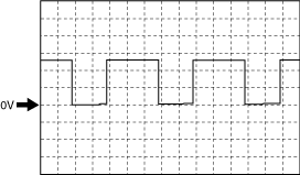
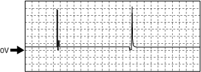
Exhaust CMP signal
adejjw00007911
|
Intake CMP signal
adejjw00007911
|
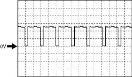
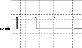
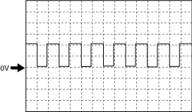
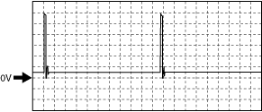
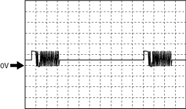
CKP signal
adejjw00007912
|
Electric variable valve timing driver (diagnostic) signal
adejjw00007913
|
Generator output voltage (without i-ELOOP)
adejjw00007914
|
Generator output voltage (with i-ELOOP)
am2zzw00012352
|
Purge control
adejjw00007915
|
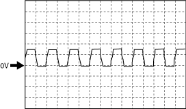
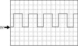
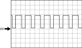
IGT1, IGT2, IGT3, IGT4 control
am2zzw00012353
|
Hydraulic variable valve timing control signal
adejjw00007917
|
Engine oil control signal
adejjw00007918
|
Electric variable valve timing control signal
adejjw00007919
|
Generator field coil control signal (without i-ELOOP)
adejjw00007920
|
Generator field coil control signal (with i-ELOOP)
am2zzw00012354
|
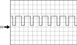
A/F sensor heater control signal
am3zzw00015902
|
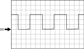
Drive-by-wire control (+) signal
Type A
am3zzw00012795
|
Type B
ac3jjw00004192
|
Fuel injection control (-) signal
adejjw00007923
|
Fuel injection control (+) signal
adejjw00007924
|
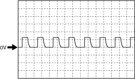
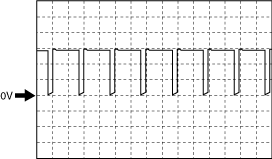
High pressure fuel pump control (+) signal
am3zzw00012796
|
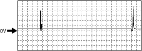
High pressure fuel pump control (-) signal
am3zzw00015903
|
HO2S heater control signal
adejjw00007927
|
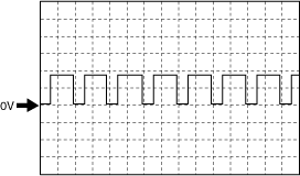
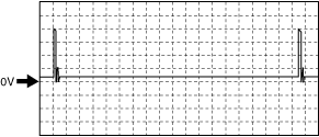
Fuel pump control signal
am3zzw00012799
|
Fuel pump control module (diagnostic) signal
am3zzw00012800
|
Using The M-MDS (PCM (200 Pin Type))
1. Connect the M-MDS to the DLC-2.
2. Switch the ignition ON (engine off).
3. Measure the PID value.
|
Item (definition) |
Unit/Condition |
Definition |
Value type |
Condition/Specification (Reference) |
PCM terminal |
|---|---|---|---|---|---|
|
AC_PRES
|
KPa {MPa}, mBar {Bar}, psi, in H20
|
Refrigerant pressure input from refrigerant pressure sensor
|
Calculation
|
• Displays refrigerant pressure
|
2AX
|
|
V
|
Refrigerant pressure sensor voltage
|
Input
|
• Refrigerant pressure is 449 kPa {4.58 kgf/cm2, 65.1 psi}: Approx. 0.76 V
• Refrigerant pressure is 729 kPa {7.43 kgf/cm2, 106 psi}: Approx. 1.18 V
|
||
|
AC_REQ
|
Off/On
|
A/C switch status received by PCM via CAN
|
Input
|
• A/C switch off: Off
• A/C switch on: On
|
CAN
(2AK, 2AL)
|
|
ACCS
|
Off/On
|
A/C relay status input from A/C relay
|
Input
|
• A/C relay off: Off
• A/C relay on: On
|
2AF
|
|
ALTF
|
%
|
Field coil current control signal output to generator
|
Calculation
|
• Ignition switched ON (engine off): 0%
• Idle: Approx. 41—54%
• Racing (Engine speed is 2,000 rpm): Approx. 24—34%
|
1BR*5, 1BE*6
|
|
ALTF_ACT*5
|
%
|
Actually measured value of field coil current signal input from generator
|
Calculation
|
• Displays actual generator field current control duty value
|
—
|
|
ALTT V*6
|
V
|
Generator output voltage
|
Input
|
• Idle (no E/L): Approx. 14 V (This is internal calculation value and differs from terminal voltage)
|
1AF
|
|
AMB_TEMP
|
°C, °F
|
Actually measured ambient temperature input from ambient temperature sensor
|
Calculation
|
• Displays ambient air temperature
|
2I
|
|
APP
|
%
|
Accelerator pedal opening angle (relative value) with the fully released status as 0% and fully depressed status as 100%
|
Calculation
|
• Accelerator pedal released: Approx. 0%
• Accelerator pedal fully depressed: Approx. 100%
|
—
|
|
APP1
|
%
|
Accelerator pedal opening angle (absolute value) input from APP sensor No.1
|
Calculation
|
• Accelerator pedal released: Approx. 16%
• Accelerator pedal fully depressed: Approx. 91%
|
2AN
|
|
V
|
APP sensor No.1 voltage
|
Input
|
• Accelerator pedal released: Approx. 0.78 V
• Accelerator pedal fully depressed: Approx. 4.54 V
|
||
|
APP2
|
%
|
Accelerator pedal opening angle (absolute value) input from APP sensor No.2
|
Calculation
|
• Accelerator pedal released: Approx. 7.84%
• Accelerator pedal fully depressed: Approx. 45.49%
|
2AS
|
|
V
|
APP sensor No.2 voltage
|
Input
|
• Accelerator pedal released: Approx. 0.39 V
• Accelerator pedal fully depressed: Approx. 2.27 V
|
||
|
ARPMDES
|
RPM
|
Target engine speed
|
Calculation
|
• Displays target engine speed
|
—
|
|
B+
|
V
|
Battery positive voltage
|
Input
|
• Displays battery voltage
|
2O
|
|
BARO
|
KPa {MPa}, mBar {Bar}, psi, in H20
|
Actually measured barometric pressure input from barometric pressure sensor built into PCM
|
Calculation
|
• Displays BARO
|
—
|
|
BATT_CUR*7
|
A
|
Battery charge/discharge current
|
Calculation
|
• Displays battery charge/discharge current value
|
CAN
(2AK, 2AL)
|
|
BATT_DAY*7
|
—
|
Number of days elapsed since current sensor initialization
|
Calculation
|
• Displays vehicle battery days in service
|
CAN
(2AK, 2AL)
|
|
BATT_RES*7
|
—
|
Battery internal resistance (estimated)
|
Calculation
|
• Displays battery inferred internal resistance
|
CAN
(2AK, 2AL)
|
|
BATT_SOC*7
|
%
|
Battery charge condition (estimated)
|
Calculation
|
• Displays battery estimated state of charge
|
CAN
(2AK, 2AL)
|
|
BATT_TEMP*7
|
°C, °F
|
Battery temperature
|
Calculation
|
• Displays battery fluid temperature
|
CAN
(2AK, 2AL)
|
|
BATT_V*7
|
V
|
Battery voltage
|
Calculation
|
• Displays battery voltage
|
CAN
(2AK, 2AL)
|
|
BBP*3
|
KPa {MPa}, mBar {Bar}, psi, in H20
|
Power brake unit vacuum input from power brake unit vacuum sensor
|
Calculation
|
• Displays power brake unit vacuum
|
2Q
|
|
V
|
Power brake unit vacuum sensor voltage
|
Input
|
Ignition switched ON
• Power brake unit vacuum is 7.96 kPa {0.0812 kgf/cm2, 1.15 psi}: approx. 0.31 V
• Power brake unit vacuum is 97.23 kPa {0.9915 kgf/cm2, 14.10 psi}: approx. 3.93 V
|
||
|
BFP*3
|
KPa {MPa}, mBar {Bar}, psi, in H20
|
Actually measured brake fluid pressure input from brake fluid pressure sensor built into DSC HU/CM via CAN
|
Calculation
|
• Displays brake fluid pressure
|
CAN
(2AK, 2AL)
|
|
BOO
|
High/Low
|
Brake switch (No.1 signal) input status
|
Calculation
|
• Brake pedal released: Low
• Brake pedal fully depressed: High
|
2G
|
|
BPA
|
High/Low
|
Brake switch (No.2 signal) input status
|
Calculation
|
• Brake pedal released: Low
• Brake pedal fully depressed: High
|
2R
|
|
CATT11_DSD
|
°C, °F
|
Estimated catalytic converter temperature
|
Calculation
|
• Displays estimated catalytic converter temperature
Idle (after warm up)
|
—
|
|
CHRGLP
|
Off/On
|
Charging system warning light illumination status
|
Calculation
|
• Charging system warning light not illuminated: Off
• Charging system warning light illuminated: On
|
—
|
|
CLU_CUT_SW*4
|
Off/On
|
Starter interlock switch status
|
Calculation
|
• Clutch pedal released: Off (starter interlock switch OFF)
• Clutch pedal fully depressed: On (starter interlock switch ON)
|
2BD
|
|
CPP*1
|
Off/On
|
Clutch pedal position
|
Calculation
|
• Clutch pedal released: Off
• Clutch pedal fully depressed: On
|
2J
|
|
CPP*4
|
%
|
Clutch pedal position input from clutch stroke sensor
|
Calculation
|
• Clutch pedal released: approx. 0.2%
• Clutch pedal fully depressed: approx. 93.5%
|
2M
|
|
CPP/PNP*1
|
Off/On
|
Shift lever position
|
Calculation
|
• Other than neutral: Off
• Neutral: On
|
1G, 1K
|
|
ECT
|
°C, °F
|
Engine coolant temperature input from ECT sensor
|
Calculation
|
• Displays ECT
|
1AK
|
|
V
|
ECT sensor voltage
|
Input
|
Ignition switched ON (engine off)
• ECT is 29 °C {84 °F}: Approx. 2.65 V
Idle (after warm up)
• ECT is 88 °C {190 °F}: Approx. 0.71 V
|
||
|
EQ_RAT11
|
—
|
Excess air factor (estimated value) to theoretical air/fuel ratio (14.7) by fuel feedback control
|
Calculation
|
Idle (after warm up)
• ECT is 89 °C {192 °F}: Approx. 1
|
—
|
|
EQ_RAT11_DSD
|
—
|
Target excess air factor (estimated value) to theoretical air/fuel ratio (14.7) by fuel feedback control
|
Calculation
|
• Indicate target lambda (Excess air factor = supplied air amount / theoretical air/fuel ratio)
|
—
|
|
ETC_ACT
|
°
|
Actual throttle valve opening angle
|
Calculation
|
Ignition switched ON (engine off)
• Accelerator pedal released: Approx. 12.89 °
• Accelerator pedal fully depressed: Approx. 86.03 °
Idle (after warm up)
• Accelerator pedal released: Approx. 2.77—2.84 ° (ECT is 89 °C {192 °F})
|
—
|
|
ETC_DSD
|
°
|
Target throttle valve opening angle
|
Calculation
|
• Displays target TP opening angle
Ignition switched ON (engine off)
|
—
|
|
%
|
Target throttle valve opening angle (percent)
|
Calculation
|
• Displays target TP opening angle (percent)
Ignition switched ON (engine off)
|
||
|
EVAPCP
|
%
|
Purge solenoid valve control duty value
|
Calculation
|
• Idle (after warm up): 0% (Engine coolant temperature 59 °C {140 °F} or less)
• Racing (Engine speed 2,000 rpm): 33—35% (ECT is 94 °C {201 °F})
• Racing (Engine speed 4,000 rpm): 53—55% (ECT is 94 °C {201 °F})
|
1AI
|
|
FAN_DUTY
|
Displays in the M-MDS but it does not operate.
|
||||
|
FAN1
|
Off/On
|
Cooling fan relay No.2 operation status
|
Calculation
|
• Cooling fan relay No.2 off: Off
• Cooling fan relay No.2 on: On
|
2AU
|
|
FAN3
|
Off/On
|
Cooling fan relay No.1 operation status
|
Calculation
|
• Cooling fan relay No.1 off: Off
• Cooling fan relay No.1 on: On
|
2AV
|
|
FIA
|
—
|
Fuel injection amount
|
Calculation
|
• Displays fuel injection amount
Idle (after warm up)
|
—
|
|
FLI
|
%
|
Fuel level
|
Calculation
|
• Fuel gauge level F: Approx. 100%
• Fuel gauge level E: Approx. 0%
|
CAN
(2AK, 2AL)
|
|
FP
|
Off/On
|
Fuel pump relay operation status
|
Calculation
|
• Ignition switched ON (engine off): Off
• Cranking: On
• Idle (after warm up): On
|
2AQ
|
|
FP_DUTY*8
|
%
|
Fuel pump control module control duty value
|
Calculation
|
• Ignition switched ON (engine off): Approx. 55.74%
• Cranking: Approx. 95%
• Idle (after warm up): Approx. 55.74%
|
2AE
|
|
FRP_A
|
KPa {MPa}, mBar {Bar}, psi, in H20
|
Actual fuel distributor pressure
|
Calculation
|
• Ignition switched ON (engine off): Approx. 3.36 MPa {34.3 kgf/cm2, 487 psi}
• Idle (after warm up): Approx. 2.96—3.13 MPa {30.2—31.9 kgf/cm2, 430—453 psi}
• Racing (engine speed is 2,000 rpm): Approx. 3.3 MPa {34 kgf/cm2, 479 psi}
• Racing (engine speed is 4,000 rpm): Approx. 4.94 MPa {50.4 kgf/cm2, 716 psi}
|
—
|
|
FRP_A_CMD
|
KPa {MPa}, mBar {Bar}, psi, in H20
|
Target fuel distributor pressure
|
Calculation
|
• Ignition switched ON (engine off): Approx. 6 MPa {61 kgf/cm2, 870 psi}
• Idle (after warm up): Approx. 3.1 MPa {32 kgf/cm2, 450 psi}
• Racing (engine speed is 2,000 rpm): Approx. 3.37 MPa {34.4 kgf/cm2, 489 psi}
• Racing (engine speed is 4,000 rpm): Approx. 4.97 MPa {50.7 kgf/cm2, 721 psi}
|
—
|
|
FRP_A_CMD_S
|
No/Yes
|
Presence/non-presence of target fuel distributor pressure
|
Calculation
|
• With fuel distributor: Yes
• Without fuel distributor: No
|
—
|
|
FRP_A_S
|
No/Yes
|
Presence/non-presence of actual fuel distributor
|
Calculation
|
• With fuel distributor: Yes
• Without fuel distributor: No
|
—
|
|
FRT_A
|
°C, °F
|
Fuel distributor temperature
|
Calculation
|
• Displays fuel distributor temperature
|
—
|
|
FT_A_S
|
No/Yes
|
Presence/non-presence of fuel distributor temperature
|
Calculation
|
• With fuel distributor: Yes
• Without fuel distributor: No
|
—
|
|
FUEL_P_DSD
|
KPa {MPa}, mBar {Bar}, psi, in H20
|
Target fuel pressure (high pressure fuel pump)
|
Calculation
|
• Displays target fuel pressure (high pressure fuel pump)
|
—
|
|
FUEL_PRES
|
KPa {MPa}, mBar {Bar}, psi, in H20
|
Fuel pressure input from fuel pressure sensor
|
Calculation
|
• Displays fuel pressure
|
1CA
|
|
V
|
Fuel pressure sensor voltage
|
Input
|
Idle (ECT 80 °C {176 °F})
• Fuel pressure is 3 MPa {31 kgf/cm2, 435 psi}: Approx. 0.9 V
|
||
|
FUELPW
|
Sec
|
Fuel injection pulse width (fuel injector energization time) output to fuel injector
|
Calculation
|
• Idle (after warm up): Approx. 1.71 ms
• Racing (engine speed is 2,000 rpm): Approx. 1.35 ms
• Racing (engine speed is 4,000 rpm): Approx. 1.21 ms
|
No.1:1DO/1DP
No.2:1DW/1DX
No.3:1EA/1EB
No.4:1DS/1DT
|
|
FUELSYS
|
OL/CL/
OL_Drive/
OL_Fault/
CL_Fault
|
Feedback status of fuel injection control is displayed
OL: Feedback control is disabled at cold engine start
CL: During feedback control by A/F sensor and HO2S
OL_Drive: While feedback control is stopped
OL_Fault: Feedback control is disable due to system malfunction
CL_Fault: During feedback control with either A/F sensor or HO2S having a malfunction
|
Calculation
|
• Idle (after warm up): OL or CL
• Racing (engine speed is 2,000 rpm): CL
• Deceleration fuel cut (accelerator pedal released from engine speed of 4,000 rpm or more): OL-Drive
|
—
|
|
GEAR*2
|
Unknown/1st/2nd/3rd/4th/5th/6th/Not in P/Park/Neutral/Drive/Reverse
|
Gear commanded
|
Calculation
|
• Selector lever at P position: Park
• Selector lever at R position: Reverse
• Selector lever at N position: Neutral
• Selector lever is in D or M position while vehicle is stopped: 1st
|
CAN
(2AK, 2AL)
|
|
HTR11
|
Off/On
|
A/F sensor heater operation status
|
Calculation
|
• Ignition switched ON (engine off): Off
• Idle (after warm up): On
|
1BY
|
|
%
|
A/F sensor heater control duty value
|
Calculation
|
• Ignition switched ON (engine off): 0%
• Idle (after warm up): 32—34%
|
||
|
HTR12
|
Off/On
|
HO2S heater operation status
|
Calculation
|
• Ignition switched ON (engine off): Off
• Idle (after warm up): On
|
2C
|
|
%
|
HO2S heater control duty value
|
Calculation
|
• Ignition switched ON (engine off): 0%
• Idle (after warm up): 41—48%
|
||
|
IAT
|
°C, °F
|
Intake air temperature (No.1) input from IAT sensor No.1
|
Calculation
|
• Displays IAT (No.1)
|
2U
|
|
V
|
IAT sensor No.1 voltage
|
Input
|
• IAT is 20 °C {68 °F}: Approx. 2.70 V
• IAT is 40 °C {104 °F}: Approx. 1.80 V
• IAT is 60 °C {140 °F}: Approx. 1.20 V
|
||
|
IAT2
|
°C, °F
|
Intake air temperature (No.2) input from IAT sensor No.2
|
Calculation
|
• Displays IAT (No.2)
|
1CE
|
|
V
|
IAT sensor No.2 voltage
|
Input
|
• IAT2 is 20 °C {68 °F}: Approx. 3.57 V
• IAT2 is 40 °C {104 °F}: Approx. 2.70 V
• IAT2 is 60 °C {140 °F}: Approx. 1.87 V
|
||
|
IMRC
|
Displays in the M-MDS but it does not operate.
|
||||
|
IMTV
|
|||||
|
INGEAR
|
Off/On
|
Gears are engaged
|
Calculation
|
MTX
• When the following conditions are satisfied: On
• Except above: Off
ATX
• Selector lever is in R, D, or M position: On
• Except above: Off
|
CAN
(2AK, 2AL)
|
|
ISC_FBK
|
%
|
ISC feedback value
|
Calculation
|
• Displays ISC feedback value
|
—
|
|
ISC_FBK_LRN
|
%
|
Learning value for calculating ISC feedback amount
|
Calculation
|
• Displays learning value for calculating ISC feedback amount
|
—
|
|
I-Stop_OFF*3
|
Off/On
|
i-stop OFF mode
|
Calculation
|
• i-stop OFF switch OFF: Off
• i-stop OFF switch ON: On
|
CAN
(2AK, 2AL)
|
|
I-Stop_TRD*3
|
Off/On
|
i-stop transmission D position selected status
|
Calculation
|
• D position:On
• Except above: Off
|
CAN
(2AK, 2AL)
|
|
I-Stop_VSP*3
|
Off/On
|
i-stop vehicle speed history flag
|
Calculation
|
• Vehicle speed in which engine stop condition is met via i-stop control is detected: On
• Except above: Off
|
CAN
(2AK, 2AL)
|
|
I-Stop_VST*3
|
Off/On
|
i-stop vehicle stop flag
|
Calculation
|
• Vehicle stop predicted: On
• Except above: Off
|
CAN
(2AK, 2AL)
|
|
IVS
|
Off Idle/Idle
|
Idle flag
|
Calculation
|
• Racing: Off Idle
• Idle: Idle
|
—
|
|
KEYST
|
—
|
Ignition key status
|
Calculation
|
• Displays ignition key status
|
—
|
|
KNOCKR
|
°
|
Ignition timing correction for suppressing engine knock (Performs retard correction (negative indication) according to the occurrence of engine knock, and it approaches approx. 0° by the advance correction due to engine knock suppression.)
|
Calculation
|
• Ignition switched ON (engine off): 0 °
• Idle (after warm up): 0 °
|
—
|
|
LOAD
|
%
|
Ratio of actual amount of intake air to the maximum air charging amount (mass volume) of cylinder
|
Calculation
|
• Idle (after warm up): Approx. 22.35%
• Racing (engine speed is 2,000 rpm): Approx. 17.25%
• Racing (engine speed is 4,000 rpm): Approx. 19.21%
|
—
|
|
LONGFT1
|
%
|
Fuel learning correction amount estimated based on A/F sensor signal
|
Calculation
|
• Idle (after warm up): Approx. −6.25%
• Racing (engine speed is 2,000 rpm): Approx. −3.9%
• Racing (engine speed is 4,000 rpm): Approx. −3.9%
|
—
|
|
LONGFT12
|
%
|
Fuel learning correction amount estimated based on HO2S signal
|
Calculation
|
• Idle (after warm up): 0%
|
—
|
|
LOW_OIL
|
Never Detected/Detected
|
Engine oil pressure condition
• Never Detected: Engine oil pressure is high
• Detected: Engine oil pressure is low
|
Calculation
|
• Ignition switched ON (engine off): Detected
• Idle (after warm up): Detected
• Racing (engine speed is 2,000—4,000 rpm): Never Detected
|
1P
|
|
LRN_KCS
|
—
|
Knock control system learning value
|
Calculation
|
• Displays knock control system learning value
|
—
|
|
M_GEAR*1
|
Neutral/1st gear/2nd gear/3rd gear/4th gear/5th gear/6th gear/Reverse/Undefined/Auto/In_Progress/YSF/Error
|
Manual gear position
|
Calculation
|
• Displays manual gear position
|
CAN
(2AK, 2AL)
|
|
MAF
|
g/Sec
|
Mass air flow input from MAF sensor
|
Calculation
|
• Displays MAF
|
2BC
|
|
V
|
MAF sensor voltage
|
Input
|
• Ignition switched ON (engine off) (MAF: 0.59 g/s {0.078 lb/min}): Approx. 0.72 V
• Idle (after warm up) (MAF: 2.17 g/s {0.287 lb/min}): Approx. 0.97 V
• Racing (engine speed is 2,000 rpm) (MAF: 4.73 g/s {0.626 lb/min}): Approx. 1.26 V
|
||
|
MAP
|
KPa {MPa}, mBar {Bar}, psi, in H20
|
Manifold absolute pressure input from MAP sensor
|
Calculation
|
• Displays MAP
|
1BW
|
|
MAP_V
|
V
|
MAP sensor voltage
|
Input
|
• Ignition switched ON (engine off) (MAP:101 kPa {1.03 kgf/cm2, 14.6 psi}): Approx. 4.12 V
• Idle (after warm up) (MAP: 33 kPa {0.34 kgf/cm2, 4.8 psi}): Approx. 1.9 V
• Racing (engine speed is 2,000 rpm) (MAP: 26 kPa {0.27 kgf/cm2, 3.8 psi}): Approx. 1.23 V
|
|
|
MF_CAT1
|
—
|
Number of misfires in No.1 cylinder leading to catalytic converter temperature increase (catalytic converter temperature increases due to fuel combustion around catalytic converter after misfire)
|
Calculation
|
• Displays number of misfires corresponding to possible catalytic converter damage (No.1 cylinder)
|
—
|
|
MF_CAT_2
|
—
|
Number of misfires in No.2 cylinder leading to catalytic converter temperature increase (catalytic converter temperature increases due to fuel combustion around catalytic converter after misfire)
|
Calculation
|
• Displays number of misfires corresponding to possible catalytic converter damage (No.2 cylinder)
|
—
|
|
MF_CAT_3
|
—
|
Number of misfires in No.3 cylinder leading to catalytic converter temperature increase (catalytic converter temperature increases due to fuel combustion around catalytic converter after misfire)
|
Calculation
|
• Displays number of misfires corresponding to possible catalytic converter damage (No.3 cylinder)
|
—
|
|
MF_CAT_4
|
—
|
Number of misfires in No.4 cylinder leading to catalytic converter temperature increase (catalytic converter temperature increases due to fuel combustion around catalytic converter after misfire)
|
Calculation
|
• Displays number of misfires corresponding to possible catalytic converter damage (No.4 cylinder)
|
—
|
|
MF_CAT_FCC
|
—
|
Threshold of malfunction determination for number of misfires (total number in all cylinders) leading to catalytic converter temperature increase
|
Calculation
|
• Displays number of misfire determinations (for catalytic converter)
|
—
|
|
MF_CAT_TTL
|
—
|
Number of misfires (total number in all cylinders) leading to catalytic converter temperature increase
|
Calculation
|
• Displays number of misfires corresponding to possible catalytic converter damage (total)
|
—
|
|
MF_EMI1
|
—
|
Number of misfires in No.1 cylinder under conditions required by emission regulations
|
Calculation
|
• Displays number of misfires possibly affecting emission (No.1 cylinder)
|
—
|
|
MF_EMI_2
|
—
|
Number of misfires in No.2 cylinder under conditions required by emission regulations
|
Calculation
|
• Displays number of misfires possibly affecting emission (No.2 cylinder)
|
—
|
|
MF_EMI_3
|
—
|
Number of misfires in No.3 cylinder under conditions required by emission regulations
|
Calculation
|
• Displays number of misfires possibly affecting emission (No.3 cylinder)
|
—
|
|
MF_EMI_4
|
—
|
Number of misfires in No.4 cylinder under conditions required by emission regulations
|
Calculation
|
• Displays number of misfires possibly affecting emission (No.4 cylinder)
|
—
|
|
MF_EMI_FCC
|
—
|
Threshold of malfunction determination for number of misfires (total number in all cylinders) under conditions required by emission regulations
|
Calculation
|
• Displays number of misfire determinations (for emission)
|
—
|
|
MF_EMI_TTL
|
—
|
Number of misfires (total number in all cylinders) under conditions required by emission regulations
|
Calculation
|
• Displays number of misfires possibly affecting emission (total)
|
—
|
|
MIL
|
Off/On
|
Check engine light illumination status
|
Calculation
|
• Check engine light not illuminated: Off
• Check engine light illuminated: On
|
—
|
|
MIL_DIS
|
Km, ft, mi
|
Travelled distance since check engine light illuminated
|
Calculation
|
• Displays travelled distance since check engine light illuminated
|
—
|
|
NEUTRAL_SW1*4
|
Off/On
|
Neutral switch No.1 status
|
Calculation
|
• Neutral: On
• Other than neutral: Off
|
1K
|
|
NEUTRAL_SW2*4
|
Off/On
|
Neutral switch No.2 status
|
Calculation
|
• Neutral: On
• Other than neutral: Off
|
1G
|
|
O2S11
|
µA
|
A/F sensor current
|
Input
|
• Idle (after warm up): 0—50 µA
• Deceleration fuel cut (accelerator pedal released from engine speed of 4,000 rpm or more): Approx. 3.84 mA
|
1AB
|
|
O2S12
|
V
|
HO2S voltage
|
Input
|
• Idle (after warm up): 0—1.0 V
• Deceleration fuel cut (accelerator pedal released from engine speed of 4,000 rpm or more): Approx. 0 V
|
2AI/2AG
|
|
OIL_P_SOL
|
Off/On
|
Engine oil solenoid valve operation status
|
Calculation
|
• ECT below 98 °C {208 °F} and engine speed below 4,000 rpm: On
• ECT above 98 °C {208 °F} or engine speed above 4,000 rpm: Off
|
1AS
|
|
OIL_TEMP
|
°C, °F
|
Estimated engine oil temperature
|
Calculation
|
• Displays estimated engine oil temperature
|
—
|
|
PN_SW*2
|
Open/Closed
|
Parking/neutral
|
Calculation
|
• Selector lever at P position or N position: Closed
• Except above: Open
|
CAN
(2AK, 2AL)
|
|
RO2FT1
|
%
|
Fuel correction amount based on HO2S signal including SHRTFT12 and LONGFT12
|
Calculation
|
• Idle (after warm up): Approx. 0%
• Deceleration fuel cut (accelerator pedal released from engine speed of 4,000 rpm or more): Approx. 3.99%
|
—
|
|
RPM
|
RPM
|
Engine speed
|
Calculation
|
• Displays engine speed
|
1AD
|
|
SHRTFT1
|
%
|
Fuel feedback correction amount estimated based on A/F sensor signal
|
Calculation
|
• Idle (after warm up): Approx. 0%
• Racing (engine speed is 2,000 rpm): Approx. 1.56%
• Racing (engine speed is 4,000 rpm): Approx. −4.68%
|
—
|
|
SHRTFT12
|
%
|
Fuel feedback correction amount estimated based on HO2S signal
|
Calculation
|
• Idle (after warm up): 0%
|
—
|
|
SPARKADV
|
°
|
Ignition timing
|
Calculation
|
• Displays ignition timing
|
—
|
|
TP_REL
|
%
|
Throttle valve opening angle (relative value) with value at throttle valve fully close timing as the start point
|
Calculation
|
• Accelerator pedal released: Approx. 12%
• Accelerator pedal fully depressed: Approx. 82%
|
—
|
|
TP1
|
%
|
Throttle valve position No.1
|
Calculation
|
• Accelerator pedal released: Approx. 22%
• Accelerator pedal fully depressed: Approx. 92%
|
1BP
|
|
V
|
TP sensor No.1 voltage
|
Input
|
• Accelerator pedal released: Approx. 1.11 V
• Accelerator pedal fully depressed: Approx. 4.59 V
|
||
|
TP2
|
%
|
Throttle valve position No.2
|
Calculation
|
• Accelerator pedal released: Approx. 22%
• Accelerator pedal fully depressed: Approx. 92%
|
1BU
|
|
V
|
TP sensor No.2 voltage
|
Input
|
• Accelerator pedal released: Approx. 3.92 V
• Accelerator pedal fully depressed: Approx. 0.41 V
|
||
|
TPCT
|
V
|
TP sensor No.1 minimum voltage at CTP
|
Calculation
|
• Ignition switched ON (engine off): Approx. 0.5 V
|
1BP
|
|
TPCT2
|
V
|
TP sensor No.2 maximum voltage at CTP
|
Calculation
|
• Ignition switched ON (engine off): Approx. 4.5 V
|
1BU
|
|
VPWR
|
V
|
Battery positive voltage
|
Input
|
• Displays battery voltage
|
2O
|
|
VSS
|
KPH, MPH
|
Vehicle speed
|
Calculation
|
• Displays vehicle speed
|
CAN
(2AK, 2AL)
|
|
VT_EX_DES
|
°
|
4-2-1 exhaust system
• Desired intake valve timing
4-1 exhaust system
• Desired exhaust valve timing
|
Calculation
|
4-2-1 exhaust system
• Displays desired intake valve timing
Idle (after warm up)
Racing (engine speed is 2,000 rpm)
4-1 exhaust system
• Displays desired exhaust valve timing
|
—
|
|
VT_IN_ACT
|
°
|
Actual intake valve timing
|
Calculation
|
4-2-1 exhaust system
• Displays in the M-MDS but it does not operate.
4-1 exhaust system
• Displays actual intake valve timing
Idle (after warm up)
Racing (engine speed is 2,000 rpm)
|
1Y*9
|
|
VT_IN_DES
|
°
|
Desired intake valve timing
|
Calculation
|
4-2-1 exhaust system
• Displays in the M-MDS but it does not operate.
4-1 exhaust system
• Displays desired intake valve timing
Idle (after warm up)
Racing (engine speed is 2,000 rpm)
|
—
|
|
VT_EX_ACT
|
°
|
4-2-1 exhaust system
• Actual intake valve timing
4-1 exhaust system
• Actual exhaust valve timing
|
Calculation
|
4-2-1 exhaust system
• Displays actual intake valve timing
Idle (after warm up)
Racing (engine speed is 2,000 rpm)
4-1 exhaust system
• Displays actual exhaust valve timing
|
1Y*9, 1T*10
|
|
VT_EX_DUTY
|
%
|
OCV control duty value
|
Calculation
|
• Idle (after warm up): 0%
• Racing (engine speed is 2,000 rpm): Approx. 40%
|
1AN
|
Without Using the M-MDS (PCM (186 Pin Type))
Terminal voltage table (Reference)
ac5wzw00010964
|
|
Terminal |
Signal |
Connected to |
Test condition |
Voltage (V) |
inspection item |
|
|---|---|---|---|---|---|---|
|
1A*1
|
CAN_2H
|
CAN system related modules
|
Because this terminal is for CAN, integrity determination by terminal voltage is not possible.
|
• Related wiring harness
|
||
|
1B*1
|
CAN_2L
|
CAN system related modules
|
Because this terminal is for CAN, integrity determination by terminal voltage is not possible.
|
• Related wiring harness
|
||
|
1C
|
—
|
—
|
—
|
—
|
—
|
|
|
1D
|
Constant voltage (Vref)
|
Engine oil pressure sensor, engine oil temperature sensor, coolant control valve position sensor
|
Ignition switched ON (engine off)
|
Approx. 5.0
|
• Related wiring harness
|
|
|
1E
|
Constant voltage (Vref)
|
CKP sensor
|
Ignition switched ON (engine off)
|
Approx. 5.0
|
• Related wiring harness
|
|
|
1F
|
CKP
|
CKP sensor
|
(See CKP signal.)
|
• CKP sensor
• Related wiring harness
|
||
|
1G
|
—
|
—
|
—
|
—
|
—
|
|
|
1H
|
—
|
—
|
—
|
—
|
—
|
|
|
1I
|
Coolant control valve position
|
Coolant control valve position sensor
|
Because this terminal is for SENT signal, integrity determination by terminal voltage is not possible.
|
• Coolant control valve position sensor
• Related wiring harness
|
||
|
1J
|
Constant voltage (Vref)
|
MAP sensor
|
Ignition switched ON (engine off)
|
Approx. 5.0
|
• Related wiring harness
|
|
|
1K
|
Constant voltage (Vref)
|
Fuel pressure sensor
|
Ignition switched ON (engine off)
|
Approx. 5.0
|
• Related wiring harness
|
|
|
1L
|
Constant voltage (Vref)
|
TP sensor No.1, TP sensor No.2
|
Ignition switched ON (engine off)
|
Approx. 5.0
|
• Related wiring harness
|
|
|
1M
|
A/F
|
A/F sensor
|
Idle (after warm up)
|
Approx. 4.1
|
• A/F sensor
• Related wiring harness
|
|
|
1N
|
GND
|
Sensor shield
|
Under any condition
|
Below 1.0
|
• Related wiring harness
|
|
|
1O
|
TP (No.1)
|
TP sensor No.1
|
Ignition switched ON (engine off)
|
Accelerator pedal released
|
Approx. 1.14
|
• TP sensor No.1
• Related wiring harness
|
|
Accelerator pedal depressed
|
Approx. 4.69
|
|||||
|
1P
|
—
|
—
|
—
|
—
|
—
|
|
|
1Q
|
IAT (No.2)
|
IAT sensor No.2
|
Ignition switched ON (engine off)
|
IAT 0 °C
{32 °F}
|
Approx. 5.9
|
• IAT sensor No.2
• Related wiring harness
|
|
IAT 20 °C
{68 °F}
|
Approx. 2.5
|
|||||
|
IAT 40 °C
{104 °F}
|
Approx. 0.323
|
|||||
|
IAT 60 °C
{140 °F}
|
Approx. 0.0893
|
|||||
|
1R
|
GND
|
TP sensor No.1, TP sensor No.2
|
Under any condition
|
Below 1.0
|
• Related wiring harness
|
|
|
1S
|
A/F
|
A/F sensor
|
Idle (after warm up): 0 mA
|
• A/F sensor
• Related wiring harness
|
||
|
1T
|
A/F
|
A/F sensor
|
Idle (after warm up)
|
Approx. 4.18
|
• A/F sensor
• Related wiring harness
|
|
|
1U
|
GND
|
Sensor shield
|
Under any condition
|
Below 1.0
|
• Related wiring harness
|
|
|
1V
|
TP (No.2)
|
TP sensor No.2
|
Ignition switched ON (engine off)
|
Accelerator pedal released
|
Approx. 3.91
|
• TP sensor No.2
• Related wiring harness
|
|
Accelerator pedal depressed
|
Below 1.0
|
|||||
|
1W
|
Fuel pressure
|
Fuel pressure sensor
|
Idle (ECT 80°C{176 °F})
|
Approx. 1.4
|
• Fuel pressure sensor
• Related wiring harness
|
|
|
1X
|
MAP
|
MAP sensor
|
Ignition switched ON (engine off)
|
Approx. 4.15
|
• MAP sensor
• Related wiring harness
|
|
|
Idle (after warm up)
|
Approx. 1.96
|
|||||
|
Racing
(Engine speed: 2,000 rpm)
|
Approx. 1.33
|
|||||
|
1Y
|
Knocking (+)
|
KS
|
Ignition switched ON (engine off) (Use digital type voltmeter, because measurement voltage will be detected less than true voltage when using analog type voltmeter)
|
Approx. 3.27
|
• KS
• Related wiring harness
|
|
|
1Z
|
Knocking (–)
|
KS
|
Ignition switched ON (engine off) (Use digital type voltmeter, because measurement voltage will be detected less than true voltage when using analog type voltmeter)
|
Approx. 1.64
|
• KS
• Related wiring harness
|
|
|
1AA
|
—
|
—
|
—
|
—
|
—
|
|
|
1AB
|
GND
|
ECT sensor No.1, ECT sensor No.2, engine oil pressure sensor, engine oil temperature sensor
|
Ignition switched ON (engine off)
|
Below 1.0
|
• Related wiring harness
|
|
|
1AC
|
—
|
—
|
—
|
—
|
—
|
|
|
1AD*6
|
Electric variable valve timing driver (diagnostic)
|
Electric variable valve timing driver
|
• Electric variable valve timing motor/driver
• Related wiring harness
|
|||
|
1AE*6
|
Ion (No.2)
|
Ion sensor No.2
|
Idle (after warm up)
|
Approx. 4.4
|
• Ion sensor No.2
• Related wiring harness
|
|
|
1AF*6
|
Ion (No.4)
|
Ion sensor No.4
|
Idle (after warm up)
|
Approx. 4.4
|
• Ion sensor No.4
• Related wiring harness
|
|
|
1AG*4
|
Generator output voltage
|
Generator
|
• Generator
• Related wiring harness
|
|||
|
1AH
|
ECT
|
ECT sensor No.1
|
Ignition switched ON (engine off)
|
ECT 20 °C
{68 °F}
|
Approx. 3.10
|
• ECT sensor No.1
• Related wiring harness
|
|
ECT 40 °C
{104 °F}
|
Approx. 2.16
|
|||||
|
ECT 60 °C
{140 °F}
|
Approx. 1.40
|
|||||
|
ECT 80 °C
{176 °F}
|
Approx. 0.87
|
|||||
|
ECT 100 °C
{212 °F}
|
Approx. 0.54
|
|||||
|
1AI
|
GND
|
Intake CMP sensor, exhaust CMP sensor
|
Under any condition
|
Below 1.0
|
• Related wiring harness
|
|
|
1AJ
|
—
|
—
|
—
|
—
|
—
|
|
|
1AK*6
|
Ion (No.3)
|
Ion sensor No.3
|
Idle (after warm up)
|
Approx. 4.4
|
• Ion sensor No.3
• Related wiring harness
|
|
|
1AL*6
|
Ion (No.1)
|
Ion sensor No.1
|
Idle (after warm up)
|
Approx. 4.4
|
• Ion sensor No.1
• Related wiring harness
|
|
|
1AM
|
ECT
|
ECT sensor No.2
|
Ignition switched ON (engine off)
|
ECT 20 °C
{68 °F}
|
Approx. 3.10
|
• ECT sensor No.2
• Related wiring harness
|
|
ECT 40 °C
{104 °F}
|
Approx. 2.16
|
|||||
|
ECT 60 °C
{140 °F}
|
Approx. 1.40
|
|||||
|
ECT 80 °C
{176 °F}
|
Approx. 0.87
|
|||||
|
ECT 100 °C
{212 °F}
|
Approx. 0.54
|
|||||
|
1AN
|
Engine oil temperature
|
Engine oil temperature sensor
|
Ignition switched ON (engine off)
|
Approx. 3.21
|
||
|
1AO
|
—
|
—
|
—
|
—
|
—
|
|
|
1AP
|
GND
|
CKP sensor
|
Ignition switched ON (engine off)
|
Below 1.0
|
• Related wiring harness
|
|
|
1AQ*3
|
Generator field coil control
|
Generator
|
• Generator
• Related wiring harness
|
|||
|
1AR*3
|
Generator output voltage
|
Generator
|
• Generator
• Related wiring harness
|
|||
|
1AS
|
Engine oil pressure
|
Engine oil pressure sensor
|
Ignition switched ON (engine off)
|
Below 1.0
|
• Engine oil pressure sensor
• Related wiring harness
|
|
|
Idle (after warm up)
|
1.07—1.47
|
|||||
|
1AT
|
GND
|
Sensor shield
|
Ignition switched ON (engine off)
|
Below 1.0
|
• Related wiring harness
|
|
|
1AU
|
—
|
—
|
—
|
—
|
—
|
|
|
1AV
|
—
|
—
|
—
|
—
|
—
|
|
|
1AW
|
Purge control
|
Purge solenoid valve
|
(See Purge control.)
|
• Purge solenoid valve
• Related wiring harness
|
||
|
1AX
|
—
|
—
|
—
|
—
|
—
|
|
|
1AY*2
|
Neutral switch No.2
|
Neutral switch No.2
|
Ignition switched ON (engine off)
|
Neutral
|
Below 1.0
|
• Neutral switch No.2
• Related wiring harness
|
|
Except above
|
B+
|
|||||
|
1AZ*2
|
Back-up light
|
Back-up light switch
|
Shift lever is at R position
|
Below 1.0
|
• Back-up light switch
• Related wiring harness
|
|
|
Shift lever is not at R position
|
B+
|
|||||
|
1BA
|
—
|
—
|
—
|
—
|
—
|
|
|
1BB
|
—
|
—
|
—
|
—
|
—
|
|
|
1BC
|
IGT1
|
Ignition coil No.1
|
• Ignition coil No.1
• Related wiring harness
|
|||
|
1BD
|
—
|
—
|
—
|
—
|
—
|
|
|
1BE
|
—
|
—
|
—
|
—
|
—
|
|
|
1BF*2
|
Neutral position
|
Neutral switch No.1
|
Shift lever is at neutral position
|
Below 1.0
|
• Neutral switch No.1
• Related wiring harness
|
|
|
Shift lever is not at neutral position
|
B+
|
|||||
|
1BG
|
GND
|
Coolant control valve position sensor
|
Under any condition
|
Below 1.0
|
• Related wiring harness
|
|
|
1BH
|
GND
|
MAP sensor, IAT sensor No.2, fuel pressure sensor
|
Under any condition
|
Below 1.0
|
• Related wiring harness
|
|
|
1BI
|
IGT2
|
Ignition coil No.2
|
• Ignition coil No.2
• Related wiring harness
|
|||
|
1BJ
|
—
|
—
|
—
|
—
|
—
|
|
|
1BK
|
—
|
—
|
—
|
—
|
—
|
|
|
1BL
|
—
|
—
|
—
|
—
|
—
|
|
|
1BM*6
|
Electric variable valve timing motor (rotation pulse)
|
Electric variable valve timing motor
|
• Electric variable valve timing motor
• Related wiring harness
|
|||
|
1BN*6
|
Electric variable valve timing motor (rotation direction)
|
Electric variable valve timing motor
|
• Electric variable valve timing motor
• Related wiring harness
|
|||
|
1BO
|
IGT3
|
Ignition coil No.3
|
• Ignition coil No.3
• Related wiring harness
|
|||
|
1BP*4
|
Generator field coil control
|
Generator
|
• Generator
• Related wiring harness
|
|||
|
1BQ
|
—
|
—
|
—
|
—
|
—
|
|
|
1BR
|
GND
|
Sensor shield
|
Ignition switched ON (engine off)
|
Below 1.0
|
• Related wiring harness
|
|
|
1BS
|
—
|
—
|
—
|
—
|
—
|
|
|
1BT
|
Intake CMP
|
Intake CMP sensor
|
(See Intake CMP signal.)
|
• Intake CMP sensor
• Related wiring harness
|
||
|
1BU
|
IGT4
|
Ignition coil No.4
|
• Ignition coil No.4
• Related wiring harness
|
|||
|
1BV*6
|
Electric variable valve timing control
|
Electric variable valve timing driver
|
• Electric variable valve timing driver
• Related wiring harness
|
|||
|
1BW
|
—
|
—
|
—
|
—
|
—
|
|
|
1BX
|
—
|
—
|
—
|
—
|
—
|
|
|
1BY
|
—
|
—
|
—
|
—
|
—
|
|
|
1BZ
|
Exhaust CMP
|
Exhaust CMP sensor
|
(See Exhaust CMP signal.)
|
• Exhaust CMP sensor
• Related wiring harness
|
||
|
1CA
|
—
|
—
|
—
|
—
|
—
|
|
|
1CB
|
A/F sensor heater control
|
A/F sensor heater
|
• A/F sensor heater
• Related wiring harness
|
|||
|
1CC
|
—
|
—
|
—
|
—
|
—
|
|
|
1CD
|
—
|
—
|
—
|
—
|
—
|
|
|
1CE
|
—
|
—
|
—
|
—
|
—
|
|
|
1CF
|
—
|
—
|
—
|
—
|
—
|
|
|
1CG
|
—
|
—
|
—
|
—
|
—
|
|
|
1CH
|
—
|
—
|
—
|
—
|
—
|
|
|
1CI
|
—
|
—
|
—
|
—
|
—
|
|
|
1CJ
|
—
|
—
|
—
|
—
|
—
|
|
|
1CK
|
Engine oil control
|
Engine oil solenoid valve
|
(See Engine oil control signal.)
|
• Engine oil solenoid valve
• Related wiring harness
|
||
|
1CL
|
—
|
—
|
—
|
—
|
—
|
|
|
1CM
|
—
|
—
|
—
|
—
|
—
|
|
|
1CN
|
—
|
—
|
—
|
—
|
—
|
|
|
1CO
|
Hydraulic variable valve timing control
|
OCV for hydraulic variable valve timing system
|
• OCV
• Related wiring harness
|
|||
|
1CP
|
—
|
—
|
—
|
—
|
—
|
|
|
1CQ
|
Drive-by-wire control (+)
|
Throttle valve actuator
|
• Throttle valve actuator
• Related wiring harness
|
|||
|
1CR
|
Drive-by-wire control (–)
|
Throttle valve actuator
|
Idle (after warm up)
Because the drive-by-wire control (-) terminal value varies depending on the vehicle, examination using only the ICQ terminal is not possible. When performing the inspection, perform it together with the ICR terminal.
• Type A
• Type B
|
• Throttle valve actuator
• Related wiring harness
|
||
|
1CS
|
—
|
—
|
—
|
—
|
—
|
|
|
1CT
|
—
|
—
|
—
|
—
|
—
|
|
|
1CU
|
Fuel injection control (+)
|
Fuel injector No.3
|
• Fuel injector No.3
• Related wiring harness
|
|||
|
1CV
|
Fuel injection control (–)
|
Fuel injector No.3
|
• Fuel injector No.3
• Related wiring harness
|
|||
|
1CW
|
Coolant control valve control (+)
|
Coolant control valve
|
Ignition switched ON (engine off)
|
B+
|
• Coolant control valve
• Related wiring harness
|
|
|
1CX
|
Coolant control valve control (–)
|
Coolant control valve
|
Ignition switched ON (engine off)
|
B+
|
• Coolant control valve
• Related wiring harness
|
|
|
1CY
|
Fuel injection control (+)
|
Fuel injector No.2
|
• Fuel injector No.2
• Related wiring harness
|
|||
|
1CZ
|
Fuel injection control (–)
|
Fuel injector No.2
|
• Fuel injector No.2
• Related wiring harness
|
|||
|
1DA
|
—
|
—
|
—
|
—
|
—
|
|
|
1DB
|
—
|
—
|
—
|
—
|
—
|
|
|
1DC
|
Fuel injection control (+)
|
Fuel injector No.4
|
• Fuel injector No.4
• Related wiring harness
|
|||
|
1DD
|
Fuel injection control (–)
|
Fuel injector No.4
|
• Fuel injector No.4
• Related wiring harness
|
|||
|
1DE
|
—
|
—
|
—
|
—
|
—
|
|
|
1DF
|
—
|
—
|
—
|
—
|
—
|
|
|
1DG
|
Fuel injection control (+)
|
Fuel injector No.1
|
• Fuel injector No.1
• Related wiring harness
|
|||
|
1DH
|
Fuel injection control (–)
|
Fuel injector No.1
|
• Fuel injector No.1
• Related wiring harness
|
|||
|
1DI
|
High pressure fuel pump control (+)
|
High pressure fuel pump
|
• High pressure fuel pump
• Related wiring harness
|
|||
|
1DJ
|
High pressure fuel pump control (–)
|
High pressure fuel pump
|
• High pressure fuel pump
• Related wiring harness
|
|||
|
2A
|
Battery voltage
|
Battery
|
Ignition switched ON (engine off)
|
B+
|
• Battery
• Related wiring harness
|
|
|
2B
|
Main relay control
|
Main relay
|
Ignition switched ON (engine off)
|
Below 1.0
|
• Main relay
• Related wiring harness
|
|
|
2C*3
|
DC-DC converter (i-ELOOP) control
|
DC-DC converter (i-ELOOP)
|
Idle (after warm up)
|
0 or B+
|
• DC-DC converter (i-ELOOP)
• Related wiring harness
|
|
|
2D*5
|
Fuel pump control
|
Fuel pump control module
|
(See Fuel pump control signal.)
|
• Fuel pump control module
• Related wiring harness
|
||
|
2E
|
—
|
—
|
—
|
—
|
—
|
|
|
2F
|
Ignition (IG1)
|
IG1 relay
|
Ignition switched ON (engine off)
|
B+
|
• IG1 relay
• Related wiring harness
|
|
|
2G
|
—
|
—
|
—
|
—
|
—
|
|
|
2H
|
Starter cut-off control
|
Starter relay, start stop unit
|
Ignition switched ON (engine off)
|
Selector lever position is not P or N position
|
B+
|
• Starter relay
• Start stop unit
• Related wiring harness
|
|
Selector lever position is P or N position
|
Below 1.0
|
|||||
|
2I
|
—
|
—
|
—
|
—
|
—
|
|
|
2J
|
—
|
—
|
—
|
—
|
—
|
|
|
2K
|
—
|
—
|
—
|
—
|
—
|
|
|
2L
|
—
|
—
|
—
|
—
|
—
|
|
|
2M
|
—
|
—
|
—
|
—
|
—
|
|
|
2N
|
—
|
—
|
—
|
—
|
—
|
|
|
2O
|
—
|
—
|
—
|
—
|
—
|
|
|
2P
|
Brake (No.2)
|
Brake switch (No.2 signal)
|
Brake pedal released
|
Below 1.0
|
• Brake switch (No.2 signal)
• Related wiring harness
|
|
|
Brake pedal depressed
|
B+
|
|||||
|
2Q
|
—
|
—
|
—
|
—
|
—
|
|
|
2R
|
Ambient temperature
|
Ambient temperature sensor
|
Ignition switched ON (engine off)
|
AAT 20 °C
{68 °F}
|
Approx. 2.70
|
• Ambient temperature sensor
• Related wiring harness
|
|
AAT 30 °C
{104 °F}
|
Approx. 1.80
|
|||||
|
2S
|
CAN_H
|
CAN system related modules
|
Because this terminal is for CAN, integrity determination by terminal voltage is not possible.
|
• Related wiring harness
|
||
|
2T
|
CAN_L
|
CAN system related modules
|
Because this terminal is for CAN, integrity determination by terminal voltage is not possible.
|
• Related wiring harness
|
||
|
2U
|
—
|
—
|
—
|
—
|
—
|
|
|
2V
|
—
|
—
|
—
|
—
|
—
|
|
|
2W
|
—
|
—
|
—
|
—
|
—
|
|
|
2X
|
Power brake unit vacuum
|
Power brake unit vacuum sensor
|
Ignition switched ON (engine off)
|
Brake pedal depressed (10 times)
|
Approx. 4.01
|
• Power brake unit vacuum sensor
• Related wiring harness
|
|
Idle (after warm up)
|
Brake pedal released
|
Approx. 0.36—0.40
|
||||
|
2Y
|
—
|
—
|
—
|
—
|
—
|
|
|
2Z
|
—
|
—
|
—
|
—
|
—
|
|
|
2AA
|
—
|
—
|
—
|
—
|
—
|
|
|
2AB
|
Brake (No.1)
|
Brake switch (No.1 signal)
|
Brake pedal released
|
Below 1.0
|
• Brake switch (No.1 signal)
• Related wiring harness
|
|
|
Brake pedal depressed
|
B+
|
|||||
|
2AC
|
—
|
—
|
—
|
—
|
—
|
|
|
2AD
|
—
|
—
|
—
|
—
|
—
|
|
|
2AE
|
—
|
—
|
—
|
—
|
—
|
|
|
2AF
|
A/C cut-off control
|
A/C relay
|
A/C relay OFF
|
B+
|
• A/C relay
• Related wiring harness
|
|
|
A/C relay ON
|
Below 1.0
|
|||||
|
2AG
|
—
|
—
|
—
|
—
|
—
|
|
|
2AH*2
|
CPP
|
CPP switch, start stop unit
|
Clutch pedal fully depressed
|
Below 1.0
|
• CPP switch
• Start stop unit
• Related wiring harness
|
|
|
Clutch pedal released
|
B+
|
|||||
|
2AI
|
GND
|
MAF sensor, IAT sensor No.1, refrigerant pressure sensor, ambient temperature sensor, clutch stroke sensor*2, power brake unit vacuum sensor
|
Under any condition
|
Below 1.0
|
• Related wiring harness
|
|
|
2AJ
|
—
|
—
|
—
|
—
|
—
|
|
|
2AK
|
DC-DC converter control*4
|
DC-DC converter
|
Ignition switched ON (engine off)
|
Below 1.0
|
• DC-DC converter
• Related wiring harness
|
|
|
DC-DC converter (i-ELOOP) control*3
|
DC-DC converter (i-ELOOP)
|
Ignition switched ON (engine off)
|
Below 1.0
|
• DC-DC converter (i-ELOOP)
• Related wiring harness
|
||
|
2AL
|
—
|
—
|
—
|
—
|
—
|
|
|
2AM
|
Cooling fan control
|
Cooling fan relay No.2
|
Cooling fan operating
|
Below 1.0
|
• Cooling fan relay No.2
• Related wiring harness
|
|
|
Cooling fan not operating
|
B+
|
|||||
|
2AN
|
—
|
—
|
—
|
—
|
—
|
|
|
2AO
|
Constant voltage (Vref)
|
APP sensor No.2
|
Ignition switched ON (engine off)
|
Approx. 5.0
|
• Related wiring harness
|
|
|
2AP*2
|
Clutch stroke sensor
|
Clutch stroke sensor
|
Ignition switched ON (engine off)
|
Clutch pedal released
|
Approx. 4.5
|
• Clutch stroke sensor
• Related wiring harness
|
|
Clutch pedal fully depressed
|
Below 1.0
|
|||||
|
2AQ
|
—
|
—
|
—
|
—
|
—
|
|
|
2AR
|
—
|
—
|
—
|
—
|
—
|
|
|
2AS
|
Cooling fan control
|
Cooling fan relay No.1
|
Cooling fan operating
|
Below 1.0
|
• Cooling fan relay No.1
• Related wiring harness
|
|
|
Cooling fan not operating
|
B+
|
|||||
|
2AT
|
Constant voltage (Vref)
|
MAF sensor, IAT sensor No.1
|
Ignition switched ON (engine off)
|
Approx. 5.0
|
• Related wiring harness
|
|
|
2AU
|
Constant voltage (Vref)
|
Power brake unit vacuum sensor, clutch stroke sensor*2
|
Ignition switched ON (engine off)
|
Approx. 5.0
|
• Related wiring harness
|
|
|
2AV
|
Refrigerant pressure
|
Refrigerant pressure sensor
|
Refrigerant pressure: 1.0 MPa {10 kgf/cm2, 145 psi}
|
Approx. 1.58
|
• Refrigerant pressure sensor
• Related wiring harness
|
|
|
Refrigerant pressure: 1.1 MPa {11 kgf/cm2, 160 psi}
|
Approx. 1.72
|
|||||
|
Refrigerant pressure: 1.2 MPa {12 kgf/cm2, 174 psi}
|
Approx. 1.88
|
|||||
|
2AW
|
Fuel pump control
|
Fuel pump relay
|
Ignition switched ON (engine off)
|
B+
|
• Fuel pump relay
• Related wiring harness
|
|
|
Idle (after warm up)
|
Below 1.0
|
|||||
|
2AX*5
|
Fuel pump control module (diagnostic)
|
Fuel pump control module
|
• Fuel pump control module
• Related wiring harness
|
|||
|
2AY
|
—
|
—
|
—
|
—
|
—
|
|
|
2AZ
|
Constant voltage (Vref)
|
Refrigerant pressure sensor
|
Ignition switched ON (engine off)
|
Approx. 5.0
|
• Related wiring harness
|
|
|
2BA
|
Constant voltage (Vref)
|
APP sensor No.1
|
Ignition switched ON (engine off)
|
Approx. 5.0
|
• Related wiring harness
|
|
|
2BB
|
APP (No.2)
|
APP sensor No.2
|
Ignition switched ON (engine off)
|
Accelerator pedal released
|
Approx. 0.41
|
• APP sensor No.2
• Related wiring harness
|
|
Accelerator pedal depressed
|
Approx. 2.00
|
|||||
|
2BC
|
—
|
—
|
—
|
—
|
—
|
|
|
2BD
|
Selector lever position*1
|
TCM, start stop unit
|
Selector lever position is not P or N position
|
B+
|
• TCM
• Start stop unit
• Related wiring harness
|
|
|
Selector lever position is P or N position
|
Below 1.0
|
|||||
|
Starter interlock*2
|
Starter interlock switch, start stop unit
|
Clutch pedal fully depressed
|
Below 1.0
|
• Starter interlock switch
• Start stop unit
• Related wiring harness
|
||
|
Clutch pedal released
|
B+
|
|||||
|
2BE
|
Intake air
|
MAF sensor, IAT sensor No.1
|
Because this terminal is for SENT signal, integrity determination by terminal voltage is not possible.
|
• MAF sensor, IAT sensor No.1
• Related wiring harness
|
||
|
2BF
|
—
|
—
|
—
|
—
|
—
|
|
|
2BG
|
GND
|
APP sensor No.2
|
Under any condition
|
Below 1.0
|
• Related wiring harness
|
|
|
2BH
|
GND
|
APP sensor No.1
|
Under any condition
|
Below 1.0
|
• Related wiring harness
|
|
|
2BI
|
—
|
—
|
—
|
—
|
—
|
|
|
2BJ
|
HO2S heater control
|
HO2S heater
|
(See HO2S heater control signal.)
|
• HO2S heater
• Related wiring harness
|
||
|
2BK
|
HO2S (+)
|
HO2S
|
Idle (after warm up)
|
Approx. 2.15
|
• HO2S
• Related wiring harness
|
|
|
2BL
|
HO2S (–)
|
HO2S
|
Idle (after warm up)
|
Approx. 2.05
|
• HO2S
• Related wiring harness
|
|
|
2BM
|
GND
|
Sensor shield
|
Ignition switched ON (engine off)
|
Below 1.0
|
• Related wiring harness
|
|
|
2BN
|
APP (No.1)
|
APP sensor No.1
|
Ignition switched ON (engine off)
|
Accelerator pedal released
|
Approx. 0.79
|
• APP sensor No.1
• Related wiring harness
|
|
Accelerator pedal depressed
|
Approx. 3.9
|
|||||
|
2BO
|
Main power supply
|
Main relay
|
Ignition switched ON (engine off)
|
B+
|
• Main relay
• Related wiring harness
|
|
|
2BP
|
—
|
—
|
—
|
—
|
—
|
|
|
2BQ
|
GND
|
GND
|
Ignition switched ON (engine off)
|
Below 1.0
|
• Related wiring harness
|
|
|
2BR
|
Main power supply
|
Main relay
|
Ignition switched ON (engine off)
|
B+
|
• Main relay
• Related wiring harness
|
|
|
2BS
|
—
|
—
|
—
|
—
|
—
|
|
|
2BT
|
GND
|
GND
|
Ignition switched ON (engine off)
|
Below 1.0
|
• Related wiring harness
|
|
Inspection Using An Oscilloscope (Reference) (PCM (186 Pin Type))
CKP signal
am2zzw00015448
|
Electric variable valve timing driver (diagnostic) signal
adejjw00007913
|
Generator output voltage (without i-ELOOP)
adejjw00007914
|
Generator field coil control signal (with i-ELOOP)
am2zzw00012354
|
Generator output voltage (with i-ELOOP)
am2zzw00015449
|
Purge control
am2zzw00015156
|
IGT1, IGT2, IGT3, IGT4 control
am2zzw00015450
|
Electric variable valve timing motor (rotation pulse) signal
adejjw00007910
|
Electric variable valve timing motor (rotation direction) signal
adejjw00007909
|
Generator field coil control signal (without i-ELOOP)
adejjw00007920
|
Intake CMP signal
adejjw00007911
|
Electric variable valve timing control signal
am2zzw00015158
|
Exhaust CMP signal
adejjw00007911
|
A/F sensor heater control signal
am3zzw00015902
|
Engine oil control signal
am2zzw00015451
|
Hydraulic variable valve timing control signal
adejjw00007917
|
Drive-by-wire control (+) signal
Type A
am3zzw00012795
|
Type B
ac3jjw00004192
|
Fuel injection control (+) signal
am2zzw00015161
|
Fuel injection control (-) signal
am2zzw00015162
|
High pressure fuel pump control (+) signal
am2zzw00015453
|
High pressure fuel pump control (-) signal
am3zzw00015903
|
Fuel pump control signal
am2zzw00015454
|
Fuel pump control module (diagnostic) signal
am2zzw00015165
|
HO2S heater control signal
adejjw00007927
|
Using The M-MDS (PCM (186 Pin Type))
1. Connect the M-MDS to the DLC-2.
2. Switch the ignition ON (engine off).
3. Measure the PID value.
|
Item (definition) |
Unit/Condition |
Definition |
Value type |
Condition/Specification (Reference) |
PCM terminal |
|---|---|---|---|---|---|
|
AC_PRES
|
KPa {MPa}, mBar {Bar}, psi, in H20
|
Refrigerant pressure input from refrigerant pressure sensor
|
Calculation
|
• Displays refrigerant pressure
|
2AV
|
|
V
|
Refrigerant pressure sensor voltage
|
Input
|
• Refrigerant pressure is 449 kPa {4.58 kgf/cm2, 65.1 psi}: Approx. 0.76 V
• Refrigerant pressure is 729 kPa {7.43 kgf/cm2, 106 psi}: Approx. 1.18 V
|
||
|
AC_REQ
|
Off/On
|
A/C switch status received by PCM via CAN
|
Input
|
• A/C switch off: Off
• A/C switch on: On
|
CAN
(2S, 2T)
|
|
ACCS
|
Off/On
|
A/C relay status input from A/C relay
|
Input
|
• A/C relay off: Off
• A/C relay on: On
|
2AF
|
|
ALTF
|
%
|
Field coil current control signal output to generator
|
Calculation
|
• Ignition switched ON (engine off): 0%
• Idle: Approx. 41—54%
• Racing (Engine speed is 2,000 rpm): Approx. 24—34%
|
1AQ*3, 1BP*4
|
|
ALTF_ACT*3
|
%
|
Actually measured value of field coil current signal input from generator
|
Calculation
|
• Displays actual generator field current control duty value
|
—
|
|
ALTT V*4
|
V
|
Generator output voltage
|
Input
|
• Idle (no E/L): Approx. 14 V (This is internal calculation value and differs from terminal voltage)
|
1AG
|
|
AMB_TEMP
|
°C, °F
|
Actually measured ambient temperature input from ambient temperature sensor
|
Calculation
|
• Displays ambient air temperature
|
2R
|
|
APP
|
%
|
Accelerator pedal opening angle (relative value) with the fully released status as 0% and fully depressed status as 100%
|
Calculation
|
• Accelerator pedal released: Approx. 0%
• Accelerator pedal fully depressed: Approx. 100%
|
—
|
|
APP1
|
%
|
Accelerator pedal opening angle (absolute value) input from APP sensor No.1
|
Calculation
|
• Accelerator pedal released: Approx. 16%
• Accelerator pedal fully depressed: Approx. 91%
|
2BN
|
|
V
|
APP sensor No.1 voltage
|
Input
|
• Accelerator pedal released: Approx. 0.78 V
• Accelerator pedal fully depressed: Approx. 4.54 V
|
||
|
APP2
|
%
|
Accelerator pedal opening angle (absolute value) input from APP sensor No.2
|
Calculation
|
• Accelerator pedal released: Approx. 7.84%
• Accelerator pedal fully depressed: Approx. 45.49%
|
2BB
|
|
V
|
APP sensor No.2 voltage
|
Input
|
• Accelerator pedal released: Approx. 0.39 V
• Accelerator pedal fully depressed: Approx. 2.27 V
|
||
|
ARPMDES
|
RPM
|
Target engine speed
|
Calculation
|
• Displays target engine speed
|
—
|
|
B+
|
V
|
Battery positive voltage
|
Input
|
• Displays battery voltage
|
2A
|
|
BARO
|
KPa {MPa}, mBar {Bar}, psi, in H20
|
Actually measured barometric pressure input from barometric pressure sensor built into PCM
|
Calculation
|
• Displays BARO
|
—
|
|
BATT_CUR
|
A
|
Battery charge/discharge current
|
Calculation
|
• Displays battery charge/discharge current value
|
CAN
(2S, 2T)
|
|
BATT_DAY
|
—
|
Number of days elapsed since current sensor initialization
|
Calculation
|
• Displays vehicle battery days in service
|
CAN
(2S, 2T)
|
|
BATT_RES
|
—
|
Battery internal resistance (estimated)
|
Calculation
|
• Displays battery inferred internal resistance
|
CAN
(2S, 2T)
|
|
BATT_SOC
|
%
|
Battery charge condition (estimated)
|
Calculation
|
• Displays battery estimated state of charge
|
CAN
(2S, 2T)
|
|
BATT_TEMP
|
°C, °F
|
Battery temperature
|
Calculation
|
• Displays battery fluid temperature
|
CAN
(2S, 2T)
|
|
BATT_V
|
V
|
Battery voltage
|
Calculation
|
• Displays battery voltage
|
CAN
(2S, 2T)
|
|
BBP
|
KPa {MPa}, mBar {Bar}, psi, in H20
|
Power brake unit vacuum input from power brake unit vacuum sensor
|
Calculation
|
• Displays power brake unit vacuum
|
2X
|
|
V
|
Power brake unit vacuum sensor voltage
|
Input
|
Ignition switched ON
• Power brake unit vacuum is 7.96 kPa {0.0812 kgf/cm2, 1.15 psi}: approx. 0.31 V
• Power brake unit vacuum is 97.23 kPa {0.9915 kgf/cm2, 14.10 psi}: approx. 3.93 V
|
||
|
BFP
|
KPa {MPa}, mBar {Bar}, psi, in H20
|
Actually measured brake fluid pressure input from brake fluid pressure sensor built into DSC HU/CM via CAN
|
Calculation
|
• Displays brake fluid pressure
|
CAN
(2S, 2T)
|
|
BOO
|
High/Low
|
Brake switch (No.1 signal) input status
|
Calculation
|
• Brake pedal released: Low
• Brake pedal fully depressed: High
|
2AB
|
|
BPA
|
High/Low
|
Brake switch (No.2 signal) input status
|
Calculation
|
• Brake pedal released: Low
• Brake pedal fully depressed: High
|
2P
|
|
CATT11_DSD
|
°C, °F
|
Estimated catalytic converter temperature
|
Calculation
|
• Displays estimated catalytic converter temperature
Idle (after warm up)
|
—
|
|
CHRGLP
|
Off/On
|
Charging system warning light illumination status
|
Calculation
|
• Charging system warning light not illuminated: Off
• Charging system warning light illuminated: On
|
—
|
|
CLU_CUT_SW*1
|
Off/On
|
Starter interlock switch status
|
Calculation
|
• Clutch pedal released: Off (starter interlock switch OFF)
• Clutch pedal fully depressed: On (starter interlock switch ON)
|
2BD
|
|
CPP*1
|
Off/On
|
Clutch pedal position
|
Calculation
|
• Clutch pedal released: Off
• Clutch pedal fully depressed: On
|
2AH
|
|
CPP*1
|
%
|
Clutch pedal position input from clutch stroke sensor
|
Calculation
|
• Clutch pedal released: approx. 0.2%
• Clutch pedal fully depressed: approx. 93.5%
|
2AP
|
|
CPP/PNP*1
|
Off/On
|
Shift lever position
|
Calculation
|
• Other than neutral: Off
• Neutral: On
|
1BF, 1AY
|
|
ECT
|
°C, °F
|
Engine coolant temperature input from ECT sensor
|
Calculation
|
• Displays ECT
|
1AH, 1AM
|
|
V
|
ECT sensor voltage
|
Input
|
Ignition switched ON (engine off)
• ECT is 29 °C {84 °F}: Approx. 2.65 V
Idle (after warm up)
• ECT is 88 °C {190 °F}: Approx. 0.71 V
|
||
|
ENG_CL_V_POS
|
°
|
Coolant control valve opening angle
|
Calculation
|
• Displays target coolant control valve opening angle
|
—
|
|
ENG_CL_V_POS_R
|
°
|
Coolant control valve opening angle raw
|
Input
|
• Ignition switched ON (engine off): Approx. 114°
|
1I
|
|
EOL
|
mm, in
|
Engine oil level
|
Converted value
|
• Displays in the M-MDS but it does not operate.
|
—
|
|
EOP
|
KPa {MPa}, mBar {Bar}, psi, in H20
|
Engine oil pressure
|
Converted value
|
• Switch ignition ON (engine off): 0—1 kPa {0.00—0.01 kgf/cm2, 0.0—0.1 psi}
• Idle: Approx. 150 kPa {1.53 kgf/cm2, 21.8 psi}
|
1AS
|
|
EOT2
|
°C, °F
|
Engine oil temperature from engine oil level sensor
|
Converted value
|
• Displays in the M-MDS but it does not operate.
|
—
|
|
EQ_RAT11
|
—
|
Excess air factor (estimated value) to theoretical air/fuel ratio (14.7) by fuel feedback control
|
Calculation
|
Idle (after warm up)
• ECT is 89 °C {192 °F}: Approx. 1
|
—
|
|
EQ_RAT11_DSD
|
—
|
Target excess air factor (estimated value) to theoretical air/fuel ratio (14.7) by fuel feedback control
|
Calculation
|
• Indicate target lambda (Excess air factor = supplied air amount / theoretical air/fuel ratio)
|
—
|
|
ETC_ACT
|
°
|
Actual throttle valve opening angle
|
Calculation
|
Ignition switched ON (engine off)
• Accelerator pedal released: Approx. 12.89 °
• Accelerator pedal fully depressed: Approx. 86.03 °
Idle (after warm up)
• Accelerator pedal released: Approx. 2.77—2.84 ° (ECT is 89 °C {192 °F})
|
—
|
|
ETC_DSD
|
°
|
Target throttle valve opening angle
|
Calculation
|
• Displays target TP opening angle
Ignition switched ON (engine off)
|
—
|
|
%
|
Target throttle valve opening angle (percent)
|
Calculation
|
• Displays target TP opening angle (percent)
Ignition switched ON (engine off)
|
||
|
EVAPCP
|
%
|
Purge solenoid valve control duty value
|
Calculation
|
• Idle (after warm up): 0% (Engine coolant temperature 59 °C {140 °F} or less)
• Racing (Engine speed 2,000 rpm): 33—35% (ECT is 94 °C {201 °F})
• Racing (Engine speed 4,000 rpm): 53—55% (ECT is 94 °C {201 °F})
|
1AW
|
|
FAN_DUTY
|
Displays in the M-MDS but it does not operate.
|
||||
|
FAN1
|
Off/On
|
Cooling fan relay No.2 operation status
|
Calculation
|
• Cooling fan relay No.2 off: Off
• Cooling fan relay No.2 on: On
|
2AM
|
|
FAN2
|
Off/On
|
Cooling fan relay No.1 operation status
|
Calculation
|
• Cooling fan relay No.1 off: Off
• Cooling fan relay No.1 on: On
|
2AS
|
|
FIA
|
—
|
Fuel injection amount
|
Calculation
|
• Displays fuel injection amount
Idle (after warm up)
|
—
|
|
FLI
|
%
|
Fuel level
|
Calculation
|
• Fuel gauge level F: Approx. 100%
• Fuel gauge level E: Approx. 0%
|
CAN
(2S, 2T)
|
|
FP
|
Off/On
|
Fuel pump relay operation status
|
Calculation
|
• Ignition switched ON (engine off): Off
• Cranking: On
• Idle (after warm up): On
|
2AW
|
|
FP_DUTY*5
|
%
|
Fuel pump control module control duty value
|
Calculation
|
• Ignition switched ON (engine off): Approx. 55.74%
• Cranking: Approx. 95%
• Idle (after warm up): Approx. 55.74%
|
2D
|
|
FRP_A
|
KPa {MPa}, mBar {Bar}, psi, in H20
|
Actual fuel distributor pressure
|
Calculation
|
• Ignition switched ON (engine off): Approx. 3.36 MPa {34.3 kgf/cm2, 487 psi}
• Idle (after warm up): Approx. 2.96—3.13 MPa {30.2—31.9 kgf/cm2, 430—453 psi}
• Racing (engine speed is 2,000 rpm): Approx. 3.3 MPa {34 kgf/cm2, 479 psi}
• Racing (engine speed is 4,000 rpm): Approx. 4.94 MPa {50.4 kgf/cm2, 716 psi}
|
—
|
|
FRP_A_CMD
|
KPa {MPa}, mBar {Bar}, psi, in H20
|
Target fuel distributor pressure
|
Calculation
|
• Ignition switched ON (engine off): Approx. 6 MPa {61 kgf/cm2, 870 psi}
• Idle (after warm up): Approx. 3.1 MPa {32 kgf/cm2, 450 psi}
• Racing (engine speed is 2,000 rpm): Approx. 3.37 MPa {34.4 kgf/cm2, 489 psi}
• Racing (engine speed is 4,000 rpm): Approx. 4.97 MPa {50.7 kgf/cm2, 721 psi}
|
—
|
|
FRP_A_CMD_S
|
No/Yes
|
Presence/non-presence of target fuel distributor pressure
|
Calculation
|
• With fuel distributor: Yes
• Without fuel distributor: No
|
—
|
|
FRP_A_S
|
No/Yes
|
Presence/non-presence of actual fuel distributor
|
Calculation
|
• With fuel distributor: Yes
• Without fuel distributor: No
|
—
|
|
FRT_A
|
°C, °F
|
Fuel distributor temperature
|
Calculation
|
• Displays fuel distributor temperature
|
—
|
|
FT_A_S
|
No/Yes
|
Presence/non-presence of fuel distributor temperature
|
Calculation
|
• With fuel distributor: Yes
• Without fuel distributor: No
|
—
|
|
FUEL_P_DSD
|
KPa {MPa}, mBar {Bar}, psi, in H20
|
Target fuel pressure (high pressure fuel pump)
|
Calculation
|
• Displays target fuel pressure (high pressure fuel pump)
|
—
|
|
FUEL_PRES
|
KPa {MPa}, mBar {Bar}, psi, in H20
|
Fuel pressure input from fuel pressure sensor
|
Calculation
|
• Displays fuel pressure
|
1W
|
|
V
|
Fuel pressure sensor voltage
|
Input
|
Idle (ECT 80 °C {176 °F})
• Fuel pressure is 10 MPa {102 kgf/cm2, 1450 psi}: Approx. 1.4 V
|
||
|
FUELPW
|
Sec
|
Fuel injection pulse width (fuel injector energization time) output to fuel injector
|
Calculation
|
• Idle (after warm up): Approx. 1.71 ms
• Racing (engine speed is 2,000 rpm): Approx. 1.35 ms
• Racing (engine speed is 4,000 rpm): Approx. 1.21 ms
|
No.1:1DG/1DH
No.2:1CY/1CZ
No.3:1CU/1CV
No.4:1DC/1DD
|
|
FUELSYS
|
OL/CL/
OL_Drive/
OL_Fault/
CL_Fault
|
Feedback status of fuel injection control is displayed
OL: Feedback control is disabled at cold engine start
CL: During feedback control by A/F sensor and HO2S
OL_Drive: While feedback control is stopped
OL_Fault: Feedback control is disable due to system malfunction
CL_Fault: During feedback control with either A/F sensor or HO2S having a malfunction
|
Calculation
|
• Idle (after warm up): OL or CL
• Racing (engine speed is 2,000 rpm): CL
• Deceleration fuel cut (accelerator pedal released from engine speed of 4,000 rpm or more): OL-Drive
|
—
|
|
GEAR*2
|
Unknown/1st/2nd/3rd/4th/5th/6th/Not in P/Park/Neutral/Drive/Reverse
|
Gear commanded
|
Calculation
|
• Selector lever at P position: Park
• Selector lever at R position: Reverse
• Selector lever at N position: Neutral
• Selector lever is in D or M position while vehicle is stopped: 1st
|
CAN
(2S, 2T)
|
|
HTR11
|
Off/On
|
A/F sensor heater operation status
|
Calculation
|
• Ignition switched ON (engine off): Off
• Idle (after warm up): On
|
1CB
|
|
%
|
A/F sensor heater control duty value
|
Calculation
|
• Ignition switched ON (engine off): 0%
• Idle (after warm up): 32—34%
|
||
|
HTR12
|
Off/On
|
HO2S heater operation status
|
Calculation
|
• Ignition switched ON (engine off): Off
• Idle (after warm up): On
|
2BJ
|
|
%
|
HO2S heater control duty value
|
Calculation
|
• Ignition switched ON (engine off): 0%
• Idle (after warm up): 41—48%
|
||
|
IAT
|
°C, °F
|
Intake air temperature (No.1) input from IAT sensor No.1
|
Calculation
|
• Displays IAT (No.1)
|
2BE
|
|
V
|
IAT sensor No.1 voltage
|
Input
|
• IAT is 20 °C {68 °F}: Approx. 2.70 V
• IAT is 40 °C {104 °F}: Approx. 1.80 V
• IAT is 60 °C {140 °F}: Approx. 1.20 V
|
||
|
IAT2
|
°C, °F
|
Intake air temperature (No.2) input from IAT sensor No.2
|
Calculation
|
• Displays IAT (No.2)
|
1Q
|
|
V
|
IAT sensor No.2 voltage
|
Input
|
• IAT2 is 20 °C {68 °F}: Approx. 3.57 V
• IAT2 is 40 °C {104 °F}: Approx. 2.70 V
• IAT2 is 60 °C {140 °F}: Approx. 1.87 V
|
||
|
IMRC
|
Displays in the M-MDS but it does not operate.
|
||||
|
IMTV
|
|||||
|
INGEAR
|
Off/On
|
Gears are engaged
|
Calculation
|
MTX
• When the following conditions are satisfied: On
• Except above: Off
ATX
• Selector lever is in R, D, or M position: On
• Except above: Off
|
CAN
(2S, 2T)
|
|
ISC_FBK
|
%
|
ISC feedback value
|
Calculation
|
• Displays ISC feedback value
|
—
|
|
ISC_FBK_LRN
|
%
|
Learning value for calculating ISC feedback amount
|
Calculation
|
• Displays learning value for calculating ISC feedback amount
|
—
|
|
I-Stop_OFF
|
Off/On
|
i-stop OFF mode
|
Calculation
|
• i-stop OFF switch OFF: Off
• i-stop OFF switch ON: On
|
CAN
(2S, 2T)
|
|
I-Stop_TRD
|
Off/On
|
i-stop transmission D position selected status
|
Calculation
|
• D position:On
• Except above: Off
|
CAN
(2S, 2T)
|
|
I-Stop_VSP
|
Off/On
|
i-stop vehicle speed history flag
|
Calculation
|
• Vehicle speed in which engine stop condition is met via i-stop control is detected: On
• Except above: Off
|
CAN
(2S, 2T)
|
|
I-Stop_VST
|
Off/On
|
i-stop vehicle stop flag
|
Calculation
|
• Vehicle stop predicted: On
• Except above: Off
|
CAN
(2S, 2T)
|
|
IVS
|
Off Idle/Idle
|
Idle flag
|
Calculation
|
• Racing: Off Idle
• Idle: Idle
|
—
|
|
KEYST
|
—
|
Ignition key status
|
Calculation
|
• Displays ignition key status
|
—
|
|
KNOCKR
|
°
|
Ignition timing correction for suppressing engine knock (Performs retard correction (negative indication) according to the occurrence of engine knock, and it approaches approx. 0° by the advance correction due to engine knock suppression.)
|
Calculation
|
• Ignition switched ON (engine off): 0 °
• Idle (after warm up): 0 °
|
—
|
|
LOAD
|
%
|
Ratio of actual amount of intake air to the maximum air charging amount (mass volume) of cylinder
|
Calculation
|
• Idle (after warm up): Approx. 22.35%
• Racing (engine speed is 2,000 rpm): Approx. 17.25%
• Racing (engine speed is 4,000 rpm): Approx. 19.21%
|
—
|
|
LONGFT1
|
%
|
Fuel learning correction amount estimated based on A/F sensor signal
|
Calculation
|
• Idle (after warm up): Approx. −6.25%
• Racing (engine speed is 2,000 rpm): Approx. −3.9%
• Racing (engine speed is 4,000 rpm): Approx. −3.9%
|
—
|
|
LONGFT12
|
%
|
Fuel learning correction amount estimated based on HO2S signal
|
Calculation
|
• Idle (after warm up): 0%
|
—
|
|
LOW_OIL
|
Never Detected/Detected
|
Engine oil pressure condition
• Never Detected: Engine oil pressure is high
• Detected: Engine oil pressure is low
|
Calculation
|
• Displays in the M-MDS but it does not operate.
|
—
|
|
LRN_KCS
|
—
|
Knock control system learning value
|
Calculation
|
• Displays knock control system learning value
|
—
|
|
M_GEAR*1
|
Neutral/1st gear/2nd gear/3rd gear/4th gear/5th gear/6th gear/Reverse/Undefined/Auto/In_Progress/YSF/Error
|
Manual gear position
|
Calculation
|
• Displays manual gear position
|
CAN
(2S, 2T)
|
|
MAF
|
g/Sec
|
Mass air flow input from MAF sensor
|
Calculation
|
• Displays MAF
|
2BE
|
|
V
|
MAF sensor voltage
|
Input
|
• Ignition switched ON (engine off) (MAF: 0.00 g/s {0 lb/min}): Approx. 1.69 V (ECT is 53 °C {127 °F})
• Idle (after warm up) (MAF: 2.50 g/s {0.331 lb/min}): Approx. 1.89 V (ECT is 93 °C {199 °F})
• Racing (engine speed is 2,000 rpm) (MAF: 3.80 g/s {0.503 lb/min}): Approx. 2.02 V (ECT is 95 °C {203 °F})
|
||
|
MAP
|
KPa {MPa}, mBar {Bar}, psi, in H20
|
Manifold absolute pressure input from MAP sensor
|
Calculation
|
• Displays MAP
|
1X
|
|
MAP_V
|
V
|
MAP sensor voltage
|
Input
|
• Ignition switched ON (engine off) (MAP:101 kPa {1.03 kgf/cm2, 14.6 psi}): Approx. 4.12 V
• Idle (after warm up) (MAP: 33 kPa {0.34 kgf/cm2, 4.8 psi}): Approx. 1.9 V
• Racing (engine speed is 2,000 rpm) (MAP: 26 kPa {0.27 kgf/cm2, 3.8 psi}): Approx. 1.23 V
|
|
|
MF_CAT1
|
—
|
Number of misfires in No.1 cylinder leading to catalytic converter temperature increase (catalytic converter temperature increases due to fuel combustion around catalytic converter after misfire)
|
Calculation
|
• Displays number of misfires corresponding to possible catalytic converter damage (No.1 cylinder)
|
—
|
|
MF_CAT_2
|
—
|
Number of misfires in No.2 cylinder leading to catalytic converter temperature increase (catalytic converter temperature increases due to fuel combustion around catalytic converter after misfire)
|
Calculation
|
• Displays number of misfires corresponding to possible catalytic converter damage (No.2 cylinder)
|
—
|
|
MF_CAT_3
|
—
|
Number of misfires in No.3 cylinder leading to catalytic converter temperature increase (catalytic converter temperature increases due to fuel combustion around catalytic converter after misfire)
|
Calculation
|
• Displays number of misfires corresponding to possible catalytic converter damage (No.3 cylinder)
|
—
|
|
MF_CAT_4
|
—
|
Number of misfires in No.4 cylinder leading to catalytic converter temperature increase (catalytic converter temperature increases due to fuel combustion around catalytic converter after misfire)
|
Calculation
|
• Displays number of misfires corresponding to possible catalytic converter damage (No.4 cylinder)
|
—
|
|
MF_CAT_FCC
|
—
|
Threshold of malfunction determination for number of misfires (total number in all cylinders) leading to catalytic converter temperature increase
|
Calculation
|
• Displays number of misfire determinations (for catalytic converter)
|
—
|
|
MF_CAT_TTL
|
—
|
Number of misfires (total number in all cylinders) leading to catalytic converter temperature increase
|
Calculation
|
• Displays number of misfires corresponding to possible catalytic converter damage (total)
|
—
|
|
MF_EMI1
|
—
|
Number of misfires in No.1 cylinder under conditions required by emission regulations
|
Calculation
|
• Displays number of misfires possibly affecting emission (No.1 cylinder)
|
—
|
|
MF_EMI_2
|
—
|
Number of misfires in No.2 cylinder under conditions required by emission regulations
|
Calculation
|
• Displays number of misfires possibly affecting emission (No.2 cylinder)
|
—
|
|
MF_EMI_3
|
—
|
Number of misfires in No.3 cylinder under conditions required by emission regulations
|
Calculation
|
• Displays number of misfires possibly affecting emission (No.3 cylinder)
|
—
|
|
MF_EMI_4
|
—
|
Number of misfires in No.4 cylinder under conditions required by emission regulations
|
Calculation
|
• Displays number of misfires possibly affecting emission (No.4 cylinder)
|
—
|
|
MF_EMI_FCC
|
—
|
Threshold of malfunction determination for number of misfires (total number in all cylinders) under conditions required by emission regulations
|
Calculation
|
• Displays number of misfire determinations (for emission)
|
—
|
|
MF_EMI_TTL
|
—
|
Number of misfires (total number in all cylinders) under conditions required by emission regulations
|
Calculation
|
• Displays number of misfires possibly affecting emission (total)
|
—
|
|
MIL
|
Off/On
|
Check engine light illumination status
|
Calculation
|
• Check engine light not illuminated: Off
• Check engine light illuminated: On
|
—
|
|
MIL_DIS
|
Km, ft, mi
|
Travelled distance since check engine light illuminated
|
Calculation
|
• Displays travelled distance since check engine light illuminated
|
—
|
|
NEUTRAL_SW1*1
|
Off/On
|
Neutral switch No.1 status
|
Calculation
|
• Neutral: On
• Other than neutral: Off
|
1BF
|
|
NEUTRAL_SW2*1
|
Off/On
|
Neutral switch No.2 status
|
Calculation
|
• Neutral: On
• Other than neutral: Off
|
1AY
|
|
O2S11
|
µA
|
A/F sensor current
|
Input
|
• Idle (after warm up): 0—50 µA
• Deceleration fuel cut (accelerator pedal released from engine speed of 4,000 rpm or more): Approx. 3.84 mA
|
1S
|
|
O2S12
|
V
|
HO2S voltage
|
Input
|
• Idle (after warm up): 0—1.0 V
• Deceleration fuel cut (accelerator pedal released from engine speed of 4,000 rpm or more): Approx. 0 V
|
2BK/2BL
|
|
OIL_P_SOL
|
Off/On
|
Engine oil solenoid valve operation status
|
Calculation
|
• ECT below 98 °C {208 °F} and engine speed below 4,000 rpm: On
• ECT above 98 °C {208 °F} or engine speed above 4,000 rpm: Off
|
1CK
|
|
OIL_TEMP
|
°C, °F
|
Estimated engine oil temperature
|
Calculation
|
• Displays estimated engine oil temperature
|
—
|
|
PN_SW*2
|
Open/Closed
|
Parking/neutral
|
Calculation
|
• Selector lever at P position or N position: Closed
• Except above: Open
|
CAN
(2S, 2T)
|
|
RO2FT1
|
%
|
Fuel correction amount based on HO2S signal including SHRTFT12 and LONGFT12
|
Calculation
|
• Idle (after warm up): Approx. 0%
• Deceleration fuel cut (accelerator pedal released from engine speed of 4,000 rpm or more): Approx. 3.99%
|
—
|
|
RPM
|
RPM
|
Engine speed
|
Calculation
|
• Displays engine speed
|
1F
|
|
SHRTFT1
|
%
|
Fuel feedback correction amount estimated based on A/F sensor signal
|
Calculation
|
• Idle (after warm up): Approx. 0%
• Racing (engine speed is 2,000 rpm): Approx. 1.56%
• Racing (engine speed is 4,000 rpm): Approx. −4.68%
|
—
|
|
SHRTFT12
|
%
|
Fuel feedback correction amount estimated based on HO2S signal
|
Calculation
|
• Idle (after warm up): 0%
|
—
|
|
SPARKADV
|
°
|
Ignition timing
|
Calculation
|
• Displays ignition timing
|
—
|
|
TP_REL
|
%
|
Throttle valve opening angle (relative value) with value at throttle valve fully close timing as the start point
|
Calculation
|
• Accelerator pedal released: Approx. 12%
• Accelerator pedal fully depressed: Approx. 82%
|
—
|
|
TP1
|
%
|
Throttle valve position No.1
|
Calculation
|
• Accelerator pedal released: Approx. 22%
• Accelerator pedal fully depressed: Approx. 92%
|
1O
|
|
V
|
TP sensor No.1 voltage
|
Input
|
• Accelerator pedal released: Approx. 1.11 V
• Accelerator pedal fully depressed: Approx. 4.59 V
|
||
|
TP2
|
%
|
Throttle valve position No.2
|
Calculation
|
• Accelerator pedal released: Approx. 22%
• Accelerator pedal fully depressed: Approx. 92%
|
1V
|
|
V
|
TP sensor No.2 voltage
|
Input
|
• Accelerator pedal released: Approx. 3.92 V
• Accelerator pedal fully depressed: Approx. 0.41 V
|
||
|
TPCT
|
V
|
TP sensor No.1 minimum voltage at CTP
|
Calculation
|
• Ignition switched ON (engine off): Approx. 0.5 V
|
1O
|
|
TPCT2
|
V
|
TP sensor No.2 maximum voltage at CTP
|
Calculation
|
• Ignition switched ON (engine off): Approx. 4.5 V
|
1V
|
|
VPWR
|
V
|
Battery positive voltage
|
Input
|
• Displays battery voltage
|
2A
|
|
VSS
|
KPH, MPH
|
Vehicle speed
|
Calculation
|
• Displays vehicle speed
|
CAN
(2S, 2T)
|
|
VT_IN_ACT
|
°
|
Actual intake valve timing
|
Calculation
|
• Displays actual intake valve timing
Idle (after warm up)
Racing (engine speed is 2,000 rpm)
|
1BT
|
|
VT_IN_DES
|
°
|
Desired intake valve timing
|
Calculation
|
• Displays desired intake valve timing
Idle (after warm up)
Racing (engine speed is 2,000 rpm)
|
—
|
|
VT_EX_ACT
|
°
|
Actual exhaust valve timing
|
Calculation
|
• Displays actual exhaust valve timing
|
1BZ
|
|
VT_EX_DUTY
|
%
|
OCV control duty value
|
Calculation
|
• Idle (after warm up): 0%
• Racing (engine speed is 2,000 rpm): Approx. 40%
|
1CO
|