GENERATOR CONTROL [SKYACTIV-D 1.5]


id0140z5208900

Note
•  The generator output control is different whether the i-ELOOP is equipped or not. (See Without i-ELOOP.)(See With i-ELOOP.)

Without i-ELOOP


Outline

•  Idling stability has been improved by optimum control of the generator voltage according to the engine operation and electrical load conditions.
•  The PCM determines the engine operation and electrical load conditions based on the input signals from each control part to control the energization time of the generator field coils.


Block Diagram

am2zzn00003662


Operation

Determination method for target excitation current
•  The battery condition is determined based on the current sensor signal, and the target excitation current is calculated according to the battery condition.
•  If the current sensor is malfunctioning, the target excitation current is calculated from the generator target output amount (determined by battery fluid temperature, engine speed, and vehicle speed), and the actual generator rotation speed.
Determination method for field coil excitation time
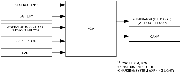
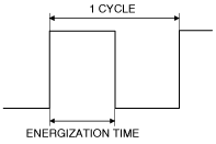
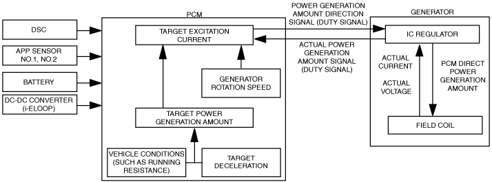
•  The field coil excitation current is increased and decreased by sending a duty signal to the power transistor built into the generator.
•  The field coil energization current changes according to changes in the power transistor excitation time by changing the duty signal duty ratio. For example, when the battery positive voltage drops, the duty ratio of the duty signal sent to the power transistor is larger, increasing the field coil excitation current.
am2zzn00003663
•  During deceleration fuel-cut, the PCM increases the generator voltage and stores electricity in the battery. At times other than deceleration, the PCM enables electric discharge from the battery to reduce the generator load.


With i-ELOOP


Outline

•  Idling stability has been improved by optimum control of the generator voltage according to the engine operation and electrical load conditions.
•  The PCM controls the variable voltage type generator so that the driver does not sense strangeness in the deceleration from the power generation torque produced during deceleration.


Block Diagram

am2zzn00003855


Operation

•  The PCM increases/decreases the field coil excitation current and controls the power generation amount of the generator by calculating the target excitation current and sending a power generation amount signal (duty signal) to the IC regulator.
Determination method for target excitation current
•  The PCM determines the generator target power generation amount based on the vehicle conditions (such as the running resistance) and the result of the estimated target deceleration*1.
•  Calculates the target excitation current based on the target power generation amount and the generator rotation speed.
*1  :The PCM calculates the target deceleration during regenerative braking according to the vehicle speed and acceleration and brake operations so that the driver does not sense strangeness in the deceleration from the power generation torque produced during deceleration.
•  The PCM gradually increases the generator output voltage considering the actual power generation amount of the generator, and controls the generator at the specified value during regenerative deceleration. It performs feedback of the actual power generation amount of the generator to control the excitation current precisely.
•  For details on the i-ELOOP operation, refer to [i-ELOOP]. (See i-ELOOP [i-ELOOP].)