 |
am2zzw00007264
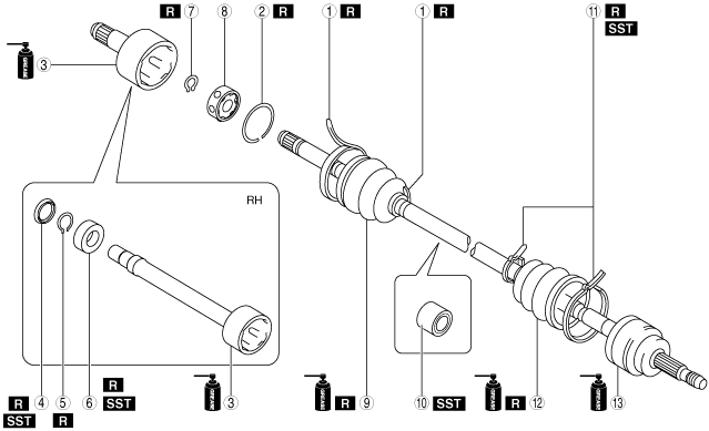
FRONT DRIVE SHAFT (DOUBLE OFFSET JOINT) DISASSEMBLY/ASSEMBLY
id031300802700
1. Disassemble in the order shown in the figure.
2. Assemble in the reverse order of disassembly.
am2zzw00007264
|
|
1
|
Boot band (transaxle side)
|
|
2
|
Clip
|
|
3
|
Outer ring
|
|
4
|
Dust cover
(See Dust Cover Disassembly Note.)
(See Dust Cover Assembly Note.)
|
|
5
|
Snap ring
|
|
6
|
Bearing
(See Bearing Disassembly Note.)
(See Bearing Assembly Note.)
|
|
7
|
Snap ring
|
|
8
|
Ball, inner ring, cage
|
|
9
|
Boot (transaxle side)
|
|
10
|
Dynamic damper [SKYACTIV-D 1.5]
(See Dynamic Damper Assembly Note.)
|
|
11
|
Boot band (wheel side)
|
|
12
|
Boot (wheel side)
|
|
13
|
Shaft and ball joint component
|
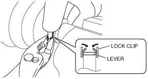
Boot Band (Transaxle Side) Disassembly Note
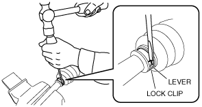
1. Using a screwdriver and hammer, lightly tap the lever of the boot band to disconnect the lock clip.
am3uuw00011877
|
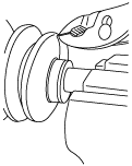
2. Remove the boot band using pliers.
am3uuw00009861
|
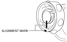
Clip, Outer Ring Disassembly Note
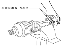
1. Place alignment marks on the shaft and outer ring.
am2zzw00007265
|
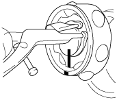
2. Remove the clip using a screwdriver.
atstjw00000061
|
3. Remove the outer ring from the shaft.
4. Wipe off grease on the outer ring using a clean rag.
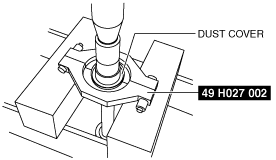
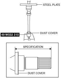
Dust Cover Disassembly Note
1. Remove the dust cover using a press and the SST.
am3uuw00011987
|
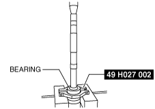
Bearing Disassembly Note
1. Remove the bearing using a press and the SST.
am3uuw00011988
|
Snap ring, Ball, Inner Ring, Cage Disassembly Note
1. Place alignment marks on the shaft, inner ring, and cage.
am2zzw00007266
|
2. Remove the snap ring using snap ring pliers.
atstjw00000063
|
3. Remove the ball, inner ring, and cage from the shaft.
4. Wipe off grease on the shaft, ball, inner ring, and cage using a clean rag.
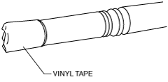
Boot (Transaxle Side) Disassembly Note
1. Wrap vinyl tape around the spline area of the shaft to prevent damage to the boot.
azzzcw00000107
|
2. Remove the boot (transaxle side).
3. Wipe off grease on the boot (transaxle side) using a clean rag.
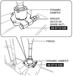
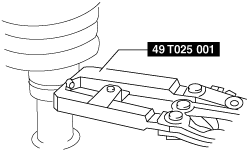
Dynamic Damper Disassembly Note
1. Remove the dynamic damper using the SST, spacers (such as spare nuts), and a press.
am2zzw00007267
|
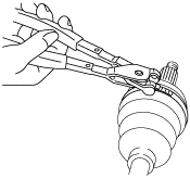
Boot Band (Wheel Side) Disassembly Note
1. Remove the boot band using end clamp pliers.
aatjjw00009768
|
Boot (Wheel Side) Disassembly Note
1. Wrap vinyl tape around the spline area of the shaft to prevent damage to the boot.
azzzcw00000107
|
2. Remove the boot (wheel side).
3. Wipe off grease on the boot (wheel side) and ball joint using a clean rag.
Boot (Wheel Side) Assembly Note
1. Insert the shaft through the boot (wheel side) with vinyl tape left wrapped around the spline area of the shaft.
2. Apply the specified grease to the ball joint and boot (wheel side).
3. Assemble the boot (wheel side) to the ball joint.
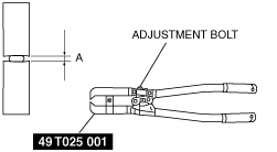
Boot Band (Wheel Side) Assembly Note
1. Adjust opening A of the SST to the standard by rotating the adjustment bolt.
am3uuw00011990
|
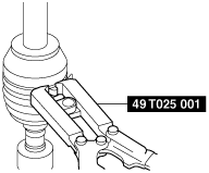
2. Crimp the boot band using the SST.
Large diameter side
atstjw00000047
|
Small diameter side
atstjw00000048
|
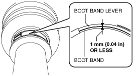
3. Verify that crimp B of the boot band is within the standard.
atstjw00000049
|
4. Verify that the boot band does not protrude from the boot band assembly area.
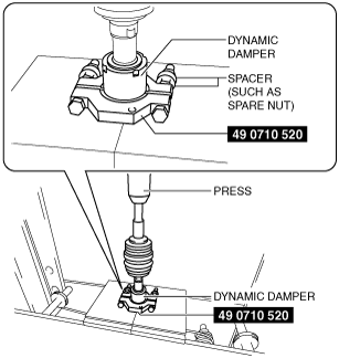
Dynamic Damper Assembly Note
1. Apply soapy water to the inside of the dynamic damper.
2. Assemble the dynamic damper using the SST, spacers (such as spare nuts), and a press.
am2zzw00012769
|
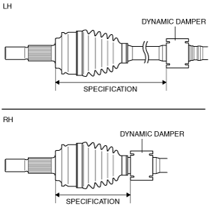
3. Verify that the installation position of the dynamic damper is within the specification.
am2zzw00007269
|
Boot (Transaxle Side) Assembly Note
1. Insert the shaft through the boot (transaxle side) with vinyl tape left wrapped around the spline area of the shaft.
2. Remove vinyl tape wrapped around the spline area of the shaft.
Ball, Inner Ring, Cage, Snap Ring Assembly Note
1. Assemble the shaft, inner ring, and cage with the alignment marks aligned.
am2zzw00007270
|
2. Assemble a new snap ring using snap ring pliers.
atstjw00000063
|
3. Verify that the snap ring is assembled correctly in the groove of the shaft.
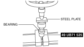
Bearing Assembly Note
1. Assemble a new bearing using the SST and a press.
am3uuw00011992
|
Dust Cover Assembly Note
1. Assemble a new dust cover using the SST and a press.
am2zzw00007271
|
2. Verify that the installation position of the dust cover is within the specification.
Outer Ring, Clip Assembly Note
1. Apply the specified grease to the outer ring and boot (transaxle side).
2. Assemble the outer ring with the alignment marks on the shaft and outer ring aligned.
am2zzw00007265
|
3. Assemble a new clip using a screwdriver.
atstjw00000061
|
4. Verify that the clip is assembled correctly in the groove of the outer ring.
5. Assemble the boot (transaxle side) to the outer ring.
6. Set the drive shaft length to the standard.
Drive shaft (double offset joint) full length (standard)
|
Engine type |
Full length (standard) |
|
|---|---|---|
|
SKYACTIV-G 1.5
|
LH
|
647.8—657.8 mm {25.51—25.89 in}
|
|
RH
|
954.1—964.1 mm {37.57—37.95 in}
|
|
|
SKYACTIV-D 1.5
|
LH
|
634—644 mm {25.0—25.3 in}
|
|
RH
|
967.1—977.1 mm {38.08—38.46 in}
|
|
7. Release any trapped air from the boot by carefully lifting up the small end of the boot with a screwdriver wrapped in a clean rag.
aatjjw00009777
|
8. Verify that the drive shaft length is within the standard when the inside of the boot is at atmospheric pressure.
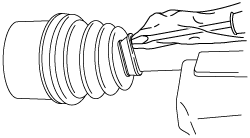
Boot Band (Transaxle Side) Assembly Note
1. Apply rust prevention oil to the inside of the boot band.
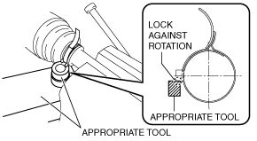
2. Lock the boot band against rotation using an appropriate tool as shown in the figure.
am3uuw00011878
|
3. Using a pair of pliers, grip the lever at the base (fulcrum point) and rotate it in the direction of the arrow.
am2zzw00007554
|
4. Hold the rotated lever with a finger and temporarily secure the lock clip by squeezing it with a pair of pliers.
am2zzw00012935
|
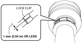
5. Lightly tap the lock clip with a hammer until the gap in the lock clip is 1 mm (0.04 in) or less.
am3uuw00011881
|
6. After assembling the boot band, perform the following verification.
am3uuw00011882
|