 |
am2zzn00002655
ON-BOARD DIAGNOSTIC SYSTEM [ABS HU/CM]
id040260181300
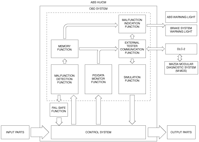
Outline
Block diagram
am2zzn00002655
|
Function
Malfunction detection function
Malfunction display function
Memory function
DTC table
|
DTC |
ABS warning light |
Brake system warning light (when parking brake is released) |
Description |
Fail-safe |
Drive cycle |
Self test type*1 |
Memory function |
|---|---|---|---|---|---|---|---|
|
C0010:01
|
Illuminates
|
Illuminates
|
ABS HU/CM internal malfunction (solenoid valve system)
|
×
|
—
|
C, D
|
×
|
|
C0011:01
|
|||||||
|
C0014:01
|
|||||||
|
C0015:01
|
|||||||
|
C0018:01
|
|||||||
|
C0019:01
|
|||||||
|
C001C:01
|
|||||||
|
C001D:01
|
|||||||
|
C0020:11
|
Illuminates
|
Not illuminate
|
Pump motor, motor relay
|
×
|
—
|
C, D
|
×
|
|
C0020:12
|
|||||||
|
C0020:13
|
|||||||
|
C0020:71
|
|||||||
|
C0030:07
|
Illuminates
|
Not illuminate*2
|
LF ABS sensor rotor
|
×
|
—
|
C, D
|
×
|
|
C0031:07
|
LF ABS wheel-speed sensor/ABS sensor rotor
|
||||||
|
C0031:11
|
Illuminates
|
Not illuminate*2
|
LF ABS wheel-speed sensor
|
×
|
—
|
C, D
|
×
|
|
C0031:15
|
|||||||
|
C0031:29
|
Illuminates
|
Not illuminate*2
|
LF ABS wheel-speed sensor/ABS sensor rotor
|
×
|
—
|
C, D
|
×
|
|
C0031:2F
|
|||||||
|
C0031:64
|
|||||||
|
C0033:07
|
Illuminates
|
Not illuminate*2
|
RF ABS sensor rotor
|
×
|
—
|
C, D
|
×
|
|
C0034:07
|
RF ABS wheel-speed sensor/ABS sensor rotor
|
||||||
|
C0034:11
|
Illuminates
|
Not illuminate*2
|
RF ABS wheel-speed sensor
|
×
|
—
|
C, D
|
×
|
|
C0034:15
|
|||||||
|
C0034:29
|
Illuminates
|
Not illuminate*2
|
RF ABS wheel-speed sensor/ABS sensor rotor
|
×
|
—
|
C, D
|
×
|
|
C0034:2F
|
|||||||
|
C0034:64
|
|||||||
|
C0036:07
|
Illuminates
|
Not illuminate*2
|
LR ABS sensor rotor
|
×
|
—
|
C, D
|
×
|
|
C0037:07
|
LR ABS wheel-speed sensor/ABS sensor rotor
|
||||||
|
C0037:11
|
Illuminates
|
Not illuminate*2
|
LR ABS wheel-speed sensor
|
×
|
—
|
C, D
|
×
|
|
C0037:15
|
|||||||
|
C0037:29
|
Illuminates
|
Not illuminate*2
|
LR ABS wheel-speed sensor/ABS sensor rotor
|
×
|
—
|
C, D
|
×
|
|
C0037:2F
|
|||||||
|
C0037:64
|
|||||||
|
C0039:07
|
Illuminates
|
Not illuminate*2
|
RR ABS sensor rotor
|
×
|
—
|
C, D
|
×
|
|
C003A:07
|
RR ABS wheel-speed sensor/ABS sensor rotor
|
||||||
|
C003A:11
|
Illuminates
|
Not illuminate*2
|
RR ABS wheel-speed sensor
|
×
|
—
|
C, D
|
×
|
|
C003A:15
|
|||||||
|
C003A:29
|
Illuminates
|
Not illuminate*2
|
RR ABS wheel-speed sensor/ABS sensor rotor
|
×
|
—
|
C, D
|
×
|
|
C003A:2F
|
|||||||
|
C003A:64
|
|||||||
|
C0040:64
|
Not illuminate
|
Not illuminate
|
Brake switch
|
×
|
—
|
C, D
|
×
|
|
C0061:54
|
Not illuminate
|
Not illuminate
|
ABS HU/CM (unperformed initialization procedure)
|
×
|
—
|
C, D
|
×
|
|
C0062:28
|
Not illuminate
|
Not illuminate
|
SAS control module
|
×
|
—
|
C, D
|
×
|
|
C0062:54
|
Not illuminate
|
Not illuminate
|
ABS HU/CM (unperformed initialization procedure)
|
×
|
—
|
C, D
|
×
|
|
C0062:64
|
Not illuminate
|
Not illuminate
|
SAS control module
|
×
|
—
|
C, D
|
×
|
|
C0062:76
|
Not illuminate
|
Not illuminate
|
SAS control module
|
×
|
—
|
C, D
|
×
|
|
U0001:88
|
Illuminates
|
Not illuminate
|
CAN line
|
×
|
—
|
C, D
|
×
|
|
U0100:00
|
Illuminates*3
|
Not illuminate
|
|||||
|
U0101:00
|
Not illuminate
|
Not illuminate
|
|||||
|
U0151:00
|
Not illuminate
|
Not illuminate
|
|||||
|
U0155:00
|
Illuminates*3
|
Not illuminate
|
|||||
|
U0401:00
|
Not illuminate
|
Not illuminate
|
Signal error from PCM
|
×
|
—
|
C, D
|
×
|
|
U0402:00
|
Not illuminate
|
Not illuminate
|
Signal error from transmission/transaxle
|
×
|
—
|
C, D
|
×
|
|
U0423:00
|
Not illuminate
|
Not illuminate
|
Signal error from instrument cluster
|
×
|
—
|
C, D
|
×
|
|
U0452:86
|
Not illuminate
|
Not illuminate
|
Signal error from SAS control module
|
×
|
—
|
C, D
|
×
|
|
U2101:00
|
Illuminates
|
Not illuminate
|
ABS HU/CM configuration
|
×
|
—
|
C, D
|
×
|
|
U2300:52
|
|||||||
|
U2300:54
|
|||||||
|
U2300:55
|
|||||||
|
U2300:56
|
|||||||
|
U2300:64
|
|||||||
|
U3000:49
|
Illuminates
|
Illuminates*3
|
ABS HU/CM internal malfunction
|
×
|
—
|
C, D
|
×
|
|
U3003:16
|
Illuminates
|
Not illuminate*4
|
Battery power supply
|
×
|
—
|
C, D
|
×
|
|
Illuminates*5*6
|
|||||||
|
U3003:17
|
Illuminates
|
Illuminates
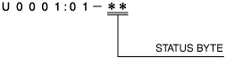
|
Status byte for DTC
am2zzn00002656
|
Fail-safe function
Fail-safe function table
|
DTC |
ABS control |
EBD control |
|---|---|---|
|
C0010:01
|
—
|
—
|
|
C0011:01
|
||
|
C0014:01
|
||
|
C0015:01
|
||
|
C0018:01
|
||
|
C0019:01
|
||
|
C001C:01
|
||
|
C001D:01
|
||
|
C0020:11
|
—
|
×
|
|
C0020:12
|
||
|
C0020:13
|
||
|
C0020:71
|
||
|
C0030:07
|
—
|
×*1
|
|
C0031:07
|
||
|
C0031:11
|
||
|
C0031:15
|
||
|
C0031:29
|
||
|
C0031:2F
|
||
|
C0031:64
|
||
|
C0033:07
|
—
|
×*1
|
|
C0034:07
|
||
|
C0034:11
|
||
|
C0034:15
|
||
|
C0034:29
|
||
|
C0034:2F
|
||
|
C0034:64
|
||
|
C0036:07
|
—
|
×*1
|
|
C0037:07
|
||
|
C0037:11
|
||
|
C0037:15
|
||
|
C0037:29
|
||
|
C0037:2F
|
||
|
C0037:64
|
||
|
C0039:07
|
—
|
×*1
|
|
C003A:07
|
||
|
C003A:11
|
||
|
C003A:15
|
||
|
C003A:29
|
||
|
C003A:2F
|
||
|
C003A:64
|
||
|
C0040:64
|
×
|
×
|
|
C0061:54
|
×
|
×
|
|
C0062:28
|
×
|
×
|
|
C0062:54
|
||
|
C0062:64
|
||
|
C0062:76
|
||
|
U0001:88
|
—
|
×
|
|
U0100:00
|
—*2
|
×
|
|
U0101:00
|
×
|
×
|
|
U0151:00
|
×
|
×
|
|
U0155:00
|
—*2
|
×
|
|
U0401:00
|
×
|
×
|
|
U0402:00
|
×
|
×
|
|
U0423:00
|
×
|
×
|
|
U0452:86
|
×
|
×
|
|
U2101:00
|
—
|
×
|
|
U2300:52
|
||
|
U2300:54
|
||
|
U2300:55
|
||
|
U2300:56
|
||
|
U2300:64
|
||
|
U3000:49
|
—
|
—*2
|
|
U3003:16
|
—
|
×*3
|
|
—*4*5
|
||
|
U3003:17
|
—
|
—
|
Snapshot data
|
Snapshot data item |
Unit |
Definition |
Data read/use method |
Corresponding data monitor items |
|---|---|---|---|---|
|
AAT
|
°C, °F
|
Ambient air temperature
|
—
|
—
|
|
ABS
|
Inactive/Active
|
Antilock braking system
|
—
|
—
|
|
APP_STATUS
|
Accelerator Pedal Off/
Under 20%/
Over 20%/
FAIL
|
Accelerator pedal position
|
—
|
—
|
|
AYC
|
Inactive/Active
|
Active yaw control
|
—
|
—
|
|
BRK_F_P_R
|
Pa, psi
|
Brake fluid line hydraulic pressure (raw value)
|
—
|
—
|
|
BTCS
|
Inactive/Active
|
Brake traction control system
|
—
|
—
|
|
CFG_STATUS
|
Config Complete/
Not Configured/
Config Error
|
Configuration status
|
—
|
—
|
|
ECT_STATUS
|
Under 0 degrees C/
0 - Under 80 degrees C/
Over 80 degrees C/
FAIL
|
Engine coolant temperature status
|
—
|
—
|
|
EDC#1
|
Inactive/Active
|
Engine drag control
|
—
|
—
|
|
IC_VPWR
|
V
|
Instrument cluster power supply
|
• The ABS HU/CM constantly receives the power supply voltage value of the instrument cluster sent via CAN signal from the instrument cluster.
• If a DTC is detected, the ABS HU/CM records the power supply voltage of the instrument cluster when the DTC was detected, and it is displayed in the M-MDS.
|
VPWR*1
|
|
IG-ON_TIMER
|
hh:mm:ss*2
|
Elapsed time since ignition was switched ON
|
• The ABS HU/CM constantly receives the elapsed time since the ignition was switched ON sent via CAN signal from the instrument cluster.
• If a DTC is detected, the ABS HU/CM records the elapsed time since the ignition was switched ON when the DTC was detected, and it is displayed in the M-MDS.
|
—
|
|
LAT_ACCL_R
|
G
|
Lateral acceleration (raw value)
|
—
|
LAT_ACCL_R
|
|
LON_ACCL_R
|
G
|
Longitudinal acceleration (raw value)
|
—
|
LON_ACCL_R
|
|
PMP_MT
|
Off/On
|
Pump motor
|
—
|
PMP_MT
|
|
PWR_MODE_KEY
|
Key Out/Key Recently Out/Key Approved (Position 0)/Post Accessory (Position 0)/Accessory (Position 1)/Post Ignition (Position 1)/Ignition On (Position 2)/Running (Position 2)/Running - Starting In Progress (Position 2)/Crank (Position 3)
|
• Key Out: Ignition switched off
• Key Recently Out (Position 0): Elapsed time within 3 s since ignition was switched off
• Accessory (Position 1): Ignition is switched to ACC
• Post Ignition (Position 2): Elapsed time within 3 s since ignition was switched ON
• Ignition On (Position 2): Ignition switched ON (engine off)
• Running (Position 2): Ignition switched ON (engine on)
• Running - Starting: Cranking condition
|
• The ABS HU/CM constantly receives the ignition switch status sent via CAN signal from the instrument cluster.
• If a DTC is detected, the ABS HU/CM records the ignition switch status when the DTC was detected, and it is displayed in the M-MDS.
|
—
|
|
RPM_STATUS
|
Engine Stop/
Under 1500 rpm/
Over 1500 rpm/
FAIL
|
Engine RPM status
|
• The ABS HU/CM constantly receives the ignition switch status sent via CAN signal from the instrument cluster.
• If a DTC is detected, the ABS HU/CM records the ignition switch status when the DTC was detected, and it is displayed in the M-MDS.
|
TACHOMTR*1
|
|
SHIFT_STATUS
|
P/N
D/
R/
FAIL
|
Shift position status
|
• The ABS HU/CM constantly receives the selector lever position sent via CAN signal from the instrument cluster.
• If a DTC is detected, the ABS HU/CM records the selector lever position when the DTC was detected, and it is displayed in the M-MDS.
|
—
|
|
STR_ANG_C
|
°
|
Steering wheel angle (calculated value)
|
—
|
—
|
|
TCS
|
Inactive/Active
|
Traction control system
|
—
|
—
|
|
TOTAL_DIST
|
km, ft, mi
|
Accumulated total traveled distance from completion of vehicle until ABS HU/CM detects DTC (Odometer value in instrument cluster)
|
The distance traveled when the ABS HU/CM detected a DTC can be calculated by performing the following procedure.
1. Verify the odometer value in the instrument cluster.
2. Verify the snap shot data item TOTAL_DIST.
3. Subtract 2 from 1.
|
—
|
|
TOTAL_TIME
|
hh:mm:ss*2
|
Accumulated total elapsed time since vehicle completion until ABS HU/CM detects a DTC
|
The elapsed time when the ABS HU/CM detected a DTC can be calculated by performing the following procedure.
1. Verify the PID item TOTAL_TIME of the instrument cluster.
2. Verify the snap shot data item TOTAL_TIME.
3. Subtract 2 from 1.
|
TOTAL_TIME*1
|
|
VPWR
|
V
|
Power supply
|
—
|
VPWR_B_SOL
|
|
VSPD
|
KPH, MPH
|
Vehicle speed
|
—
|
VSPD
|
|
VSPD_STATUS
|
Stop/
0 - 10 km/h/
Over 10 km/h/
FAIL
|
Vehicle speed status
|
• The ABS HU/CM constantly receives the vehicle speed sent via CAN signal from the instrument cluster.
• If a DTC is detected, the ABS HU/CM records the vehicle speed when the DTC was detected, and it is displayed in the M-MDS.
|
SPEEDOMTR*1
|
|
YAW_RATE_R
|
°/s
|
Yaw rate (raw value)
|
—
|
YAW_RATE_R
|
PID/data monitor function
|
Monitor item |
Unit/Operation |
Test condition |
Specification (Reference) |
|---|---|---|---|
|
M-MDS display |
|||
|
BRAKE_SW
|
Off/On
|
Brake pedal released
|
Off
|
|
Brake pedal depressed
|
On
|
||
|
LAT_ACCL_R
(raw value)
|
G
|
Vehicle stopped or driving at constant speed
|
0 G
|
|
Cornering to left
|
Changes to 0 G—positive
|
||
|
Cornering to right
|
Changes to 0 G—negative
|
||
|
LON_ACCL_C
(calculated value)
|
G
|
Vehicle stopped or driving at constant speed
|
0 G
|
|
Cornering to left
|
Changes to 0 G—positive
|
||
|
Cornering to right
|
Changes to 0 G—negative
|
||
|
LON_ACCL_R
(raw value)
|
G
|
Vehicle stopped or driving at constant speed
|
0 G
|
|
Cornering to left
|
Changes to 0 G—positive
|
||
|
Cornering to right
|
Changes to 0 G—negative
|
||
|
P_BRAKE_SW
|
Off/On
|
Parking brake lever released
|
Off
|
|
Parking brake lever pulled
|
On
|
||
|
PMP_MT
|
|
||
|
PMP_MT_SP
|
|||
|
V_INLET_LF
|
Off/On
|
Solenoid valve not activated
|
Off
|
|
Solenoid valve activated
|
On
|
||
|
V_INLET_LR
|
Off/On
|
Solenoid valve not activated
|
Off
|
|
Solenoid valve activated
|
On
|
||
|
V_INLET_RF
|
Off/On
|
Solenoid valve not activated
|
Off
|
|
Solenoid valve activated
|
On
|
||
|
V_INLET_RR
|
Off/On
|
Solenoid valve not activated
|
Off
|
|
Solenoid valve activated
|
On
|
||
|
V_OUTLET_LF
|
Off/On
|
Solenoid valve not activated
|
Off
|
|
Solenoid valve activated
|
On
|
||
|
V_OUTLET_LR
|
Off/On
|
Solenoid valve not activated
|
Off
|
|
Solenoid valve activated
|
On
|
||
|
V_OUTLET_RF
|
Off/On
|
Solenoid valve not activated
|
Off
|
|
Solenoid valve activated
|
On
|
||
|
V_OUTLET_RR
|
Off/On
|
Solenoid valve not activated
|
Off
|
|
Solenoid valve activated
|
On
|
||
|
VPWR_B_SOL
|
V
|
This PID indicates power supply voltage for ABS HU/CM.
|
|
|
VSPD
|
KPH, MPH
|
This PID indicates vehicle speed.
|
|
|
WSPD_SEN_LF
|
KPH, MPH
|
This PID indicates vehicle speed.
|
|
|
WSPD_SEN_LR
|
KPH, MPH
|
This PID indicates vehicle speed.
|
|
|
WSPD_SEN_RF
|
KPH, MPH
|
This PID indicates vehicle speed.
|
|
|
WSPD_SEN_RR
|
KPH, MPH
|
This PID indicates vehicle speed.
|
|
|
YAW_RATE_C
(calculated value)
|
°/s
|
Vehicle stopped or driving at constant speed
|
0 °/s
|
|
Cornering to left
|
Changes to 0 °/s—positive
|
||
|
Cornering to right
|
Changes to 0 °/s—negative
|
||
|
YAW_RATE_R
(raw value)
|
°/s
|
Vehicle stopped or driving at constant speed
|
0 °/s
|
|
Cornering to left
|
Changes to 0 °/s—positive
|
||
|
Cornering to right
|
Changes to 0 °/s—negative
|
||
Simulation function
|
Simulation item |
Output part |
Operation |
Operating condition |
|---|---|---|---|
|
PMP_MT_SP
|
Pump motor
|
Off/On
|
Switch the ignition ON
|
|
V_INLET_LF
|
LF inlet solenoid valve
|
||
|
V_INLET_LR
|
LR inlet solenoid valve
|
||
|
V_INLET_RF
|
RF inlet solenoid valve
|
||
|
V_INLET_RR
|
RR inlet solenoid valve
|
||
|
V_OUTLET_LF
|
LF outlet solenoid valve
|
||
|
V_OUTLET_LR
|
LR outlet solenoid valve
|
||
|
V_OUTLET_RF
|
RF outlet solenoid valve
|
||
|
V_OUTLET_RR
|
RR outlet solenoid valve
|
External tester communication function
|
Diagnostic function name |
Signal received |
Signal sent |
|---|---|---|
|
Malfunction detection function
|
DTC verification signal
|
DTC(s)
|
|
PID/data monitor function
|
Command signal to read selected monitor item
|
Monitored data for requested monitor item
|
|
Simulation function
|
Operation command signal for selected simulation item
|
Output part drive signal
|