|
am2zzw00010070
CLUTCH MASTER CYLINDER REMOVAL/INSTALLATION [F65M-R]
id0510q1156800
Removal
1. Disconnect the negative battery cable. (See NEGATIVE BATTERY CABLE DISCONNECTION/CONNECTION.)
2. Remove the air cleaner, air hose and fresh air duct as a single unit. (L.H.D.) (See INTAKE-AIR SYSTEM REMOVAL/INSTALLATION [SKYACTIV-G 1.3, SKYACTIV-G 1.5].)
3. Remove the battery tray and PCM component. (L.H.D.) (See BATTERY REMOVAL/INSTALLATION [SKYACTIV-G 1.3, SKYACTIV-G 1.5].)
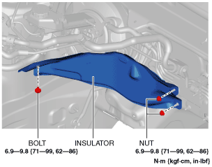
4. Remove the insulator. (R.H.D.)
am2zzw00010070
|
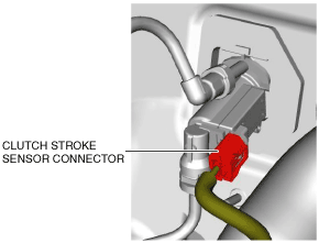
5. Disconnect the clutch stroke sensor connector.
am2zzw00014392
|
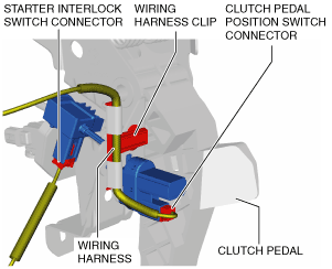
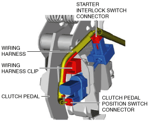
6. Disconnect the connectors and wiring harness clip shown in the figure from the clutch pedal and set the wiring harness aside.
L.H.D.
am2zzw00014393
|
R.H.D.
am2zzw00014394
|
7. Remove the clutch pedal position switch. (See CLUTCH PEDAL POSITION SWITCH REMOVAL/INSTALLATION [F65M-R])
8. Remove the starter interlock switch. (See STARTER INTERLOCK SWITCH REMOVAL/INSTALLATION [F65M-R].)
9. Remove the joint cover. (See STEERING WHEEL AND COLUMN REMOVAL/INSTALLATION.)
10. Disconnect the intermediate shaft from the steering gear and linkage. (See STEERING WHEEL AND COLUMN REMOVAL/INSTALLATION.)
11. Disconnect the clutch pipe No.1 from clutch master cylinder, and plug it to avoid clutch fluid leakage. (See CLUTCH PIPE AND HOSE REMOVAL/INSTALLATION [F65M-R].)
12. Disconnect the clutch reserve hose from clutch master cylinder, and plug it to avoid clutch fluid leakage. (See CLUTCH PIPE AND HOSE REMOVAL/INSTALLATION [F65M-R].)
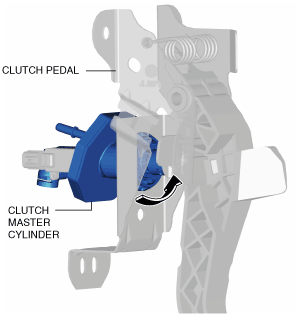
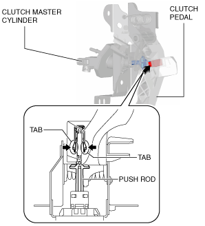
13. Remove the clutch master cylinder using the following procedure:
am2zzw00010072
|
am2zzw00014075
|
am2zzw00014076
|
Installation
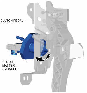
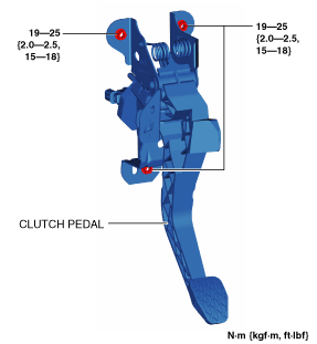
1. Install the clutch master cylinder using the following procedure:
am2zzw00014076
|
am2zzw00014077
|
am2zzw00010076
|
2. Connect the clutch reserve hose to clutch master cylinder. (See CLUTCH PIPE AND HOSE REMOVAL/INSTALLATION [F65M-R].)
3. Connect the clutch pipe No.1 to clutch master cylinder. (See CLUTCH PIPE AND HOSE REMOVAL/INSTALLATION [F65M-R].)
4. Install the intermediate shaft from the steering gear and linkage. (See STEERING WHEEL AND COLUMN REMOVAL/INSTALLATION.)
5. Install the joint cover. (See STEERING WHEEL AND COLUMN REMOVAL/INSTALLATION.)
6. Bleed the air from the clutch system. (See CLUTCH FLUID REPLACEMENT/AIR BLEEDING [F65M-R].)
7. Inspect the clutch pedal height, and verify that the clutch pedal is installed correctly. (See CLUTCH PEDAL INSPECTION [F65M-R].)
8. Install a new starter interlock switch. (See STARTER INTERLOCK SWITCH REMOVAL/INSTALLATION [F65M-R].)
9. Install a new clutch pedal position switch. (See CLUTCH PEDAL POSITION SWITCH REMOVAL/INSTALLATION [F65M-R].)
10. Connect the clutch stroke sensor connector.
am2zzw00014392
|
11. Connect the connectors, wiring harness clip and wiring harness shown in the figure to the clutch pedal.
L.H.D.
am2zzw00014393
|
R.H.D.
am2zzw00014394
|
12. Install the insulator. (R.H.D.)
am2zzw00010077
|
13. Install the air cleaner, air hose and fresh air duct as a single unit. (L.H.D.) (See INTAKE-AIR SYSTEM REMOVAL/INSTALLATION [SKYACTIV-G 1.3, SKYACTIV-G 1.5].)
14. Install the battery tray and PCM component. (L.H.D.) (See BATTERY REMOVAL/INSTALLATION [SKYACTIV-G 1.3, SKYACTIV-G 1.5].)
15. Connect the negative battery cable. (See NEGATIVE BATTERY CABLE DISCONNECTION/CONNECTION.)
16. Fully depress the clutch pedal, and verify that the engine starts.