 |
am2zzn00002515
SYNCHRONIZER MECHANISM [F66M-R]
id0515n2284000
Purpose, Function
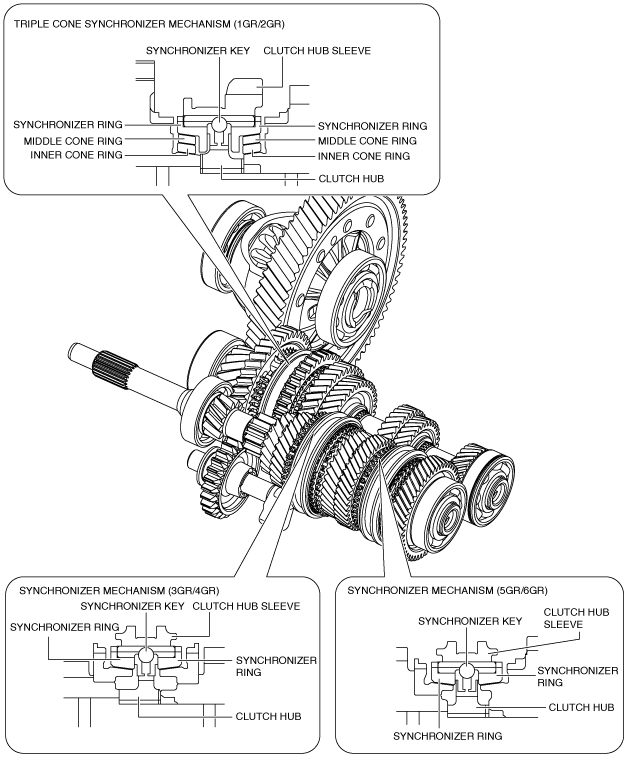
Construction
am2zzn00002515
|
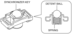
Detent ball-type synchronizer key
am2zzn00002516
|
Reverse pre-balk mechanism
Operation
1GR, 2GR operation
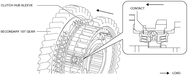
1. When the clutch hub sleeve moves toward the secondary 1st gear side, the synchronizer key follows, and the synchronizer key contacts the end surface of the synchronizer ring.
am2zzn00002517
|
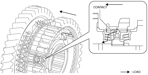
2. When the clutch hub sleeve moves toward the secondary 1st gear side, the synchronizer key which follows applies load to the synchronizer ring, and the load is transmitted from the synchronizer ring to the middle cone ring, inner cone ring, and the gear.
am2zzn00002518
|
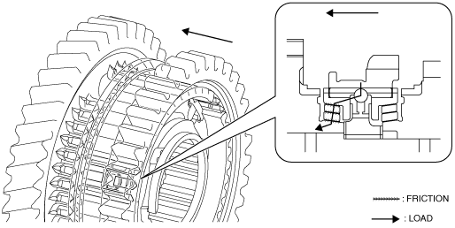
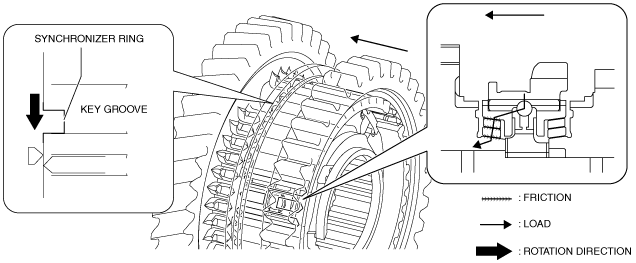
3. The friction force on the contacting surface of the parts is generated by applying load to the parts between the synchronizer ring and the gear.
am2zzn00002519
|
4. For the friction force on the parts, the synchronizer ring rotates only the groove gap of the clutch hub keys.
am2zzn00002520
|
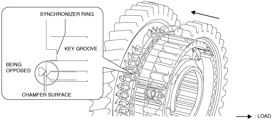
5. Because the synchronizer ring rotates, the spline of the clutch hub sleeve which moves toward the secondary 1st gear side and the chamfer of the synchronizer ring are opposed to each other.
am2zzn00002521
|
6. When the clutch hub sleeve moves toward the secondary 1st gear side, the transmitted load to the gear from the clutch hub sleeve increases because the spline of the clutch hub sleeve pushes the chamfer of the synchronizer ring.
am2zzn00002522
|
7. The friction force on the contacting surface of the parts is increased by increasing the load transmitted from the clutch hub sleeve to the gear.
am2zzn00002519
|
8. The increased friction force decreases the difference in rotation speed between the synchronizer ring, middle cone ring, inner cone ring, and the gear and the rotation speed for the parts is synchronized.
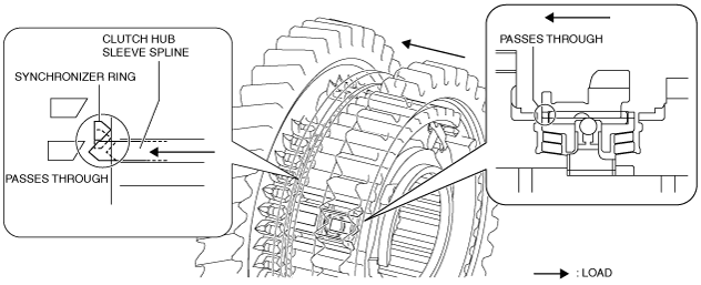
9. When synchronization in rotation speed of the gear and the clutch hub sleeve is performed, the spline of the clutch hub sleeve passes through the synchronizer ring.
am2zzn00002523
|
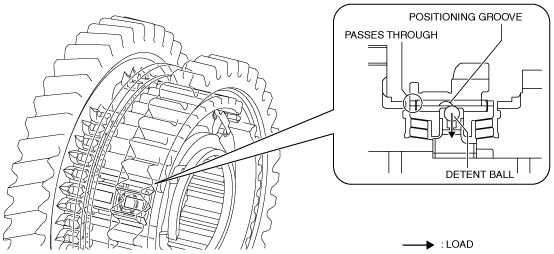
10. When the spline of the clutch hub sleeve passes through the synchronizer ring, the clutch hub sleeve presses down the detent ball and the detent ball is removed from the positioning groove of the clutch hub sleeve because the clutch hub sleeve moves toward the secondary 1st gear side.
am2zzn00002524
|
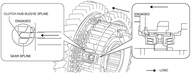
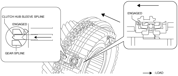
11. When the clutch hub sleeve moves toward the secondary 1st gear side, the spline of the clutch hub sleeve and the spline of the gear are engaged, and the shifting operation is completed.
am2zzn00002525
|
3GR, 4GR, 5GR, 6GR operation
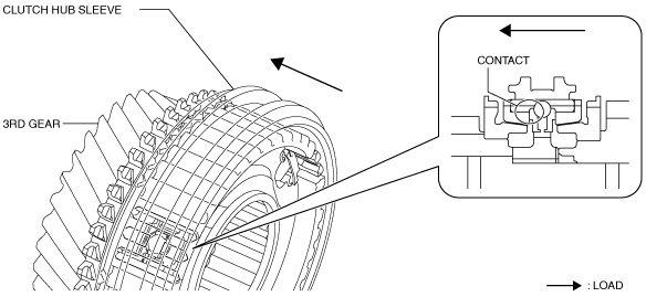
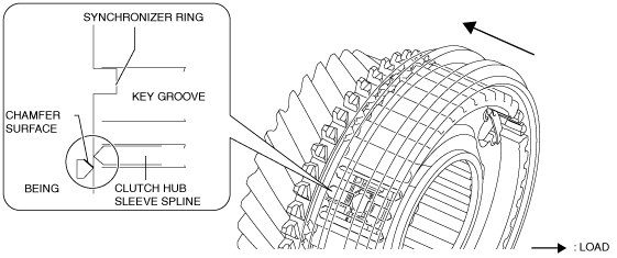
1. When the clutch hub sleeve moves toward the 3rd gear side, the synchronizer key follows, and the synchronizer key contacts the end surface of the synchronizer ring.
am2zzn00002526
|
2. When the clutch hub sleeve moves toward the 3rd gear side, the following synchronizer key applies load to the synchronizer ring, and the load is transmitted from the synchronizer ring to the gear.
am2zzn00002527
|
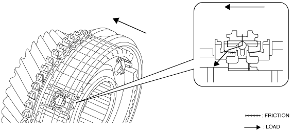
3. The friction force on the contacting surface of the synchronizer ring and the gear is generated by applying load to the parts between the synchronizer ring and the gear.
am2zzn00002528
|
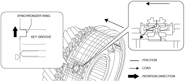
4. For the friction force of the synchronizer ring and the gear, synchronizer ring rotates only the key groove gap of the clutch hub.
am2zzn00002529
|
5. Because the synchronizer ring rotates, the spline of the clutch hub sleeve which moves toward the 3rd gear side and the chamfer of the synchronizer ring are opposed to each other.
am2zzn00002530
|
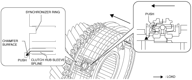
6. When the clutch hub sleeve moves toward the 3rd gear, the load transmitted from the clutch hub sleeve to the gear increases because the spline of the clutch hub sleeve pushes the chamfer of the synchronizer ring.
am2zzn00002531
|
7. The friction force on the contacting surface of the parts is increased by increasing the load transmitted from the clutch hub sleeve to the gear.
am2zzn00002532
|
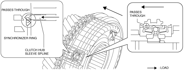
8. The increased friction force disappears the difference in the rotation speed between the synchronizer ring and the gear, and the rotation is synchronized.
9. When synchronization in rotation speed of the gear and the clutch hub sleeve is performed, the spline of the clutch hub sleeve passes through the synchronizer ring.
am2zzn00002533
|
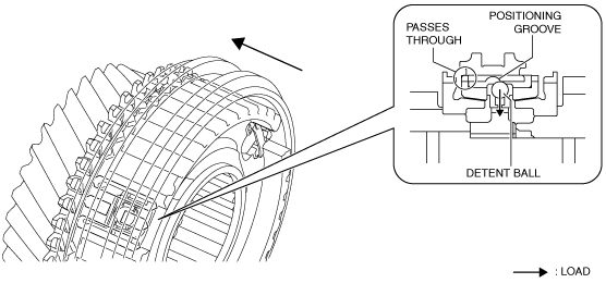
10. When the spline of the clutch hub sleeve passes through the synchronizer ring, the clutch hub sleeve presses down the ball and the ball is removed from the positioning groove of the clutch hub sleeve because the clutch hub sleeve moves toward the 3rd gear side.
am2zzn00002534
|
11. When the clutch hub sleeve moves toward the 3rd gear side, the spline of the clutch hub sleeve and the spline of the gear are engaged, and the shifting operation is completed.
am2zzn00002535
|