 |
adejjw00010833
OIL COOLER REMOVAL/INSTALLATION [CW6A-EL]
id0517l1117500
Water Hose (SKYACTIV-G 1.3, SKYACTIV-G 1.5 (Without Coolant Control Valve))
1. Disconnect the negative battery cable. (See NEGATIVE BATTERY CABLE DISCONNECTION/CONNECTION.)
2. Remove the air cleaner and air hose as a single unit. (See INTAKE-AIR SYSTEM REMOVAL/INSTALLATION [SKYACTIV-G 1.3, SKYACTIV-G 1.5].)
3. Remove the battery tray and PCM component. (See BATTERY REMOVAL/INSTALLATION [SKYACTIV-G 1.3, SKYACTIV-G 1.5].)
4. Remove the front under cover No.2. (See FRONT UNDER COVER No.2 REMOVAL/INSTALLATION.)
5. Drain the engine coolant. (See ENGINE COOLANT REPLACEMENT [SKYACTIV-G 1.3, SKYACTIV-G 1.5].)
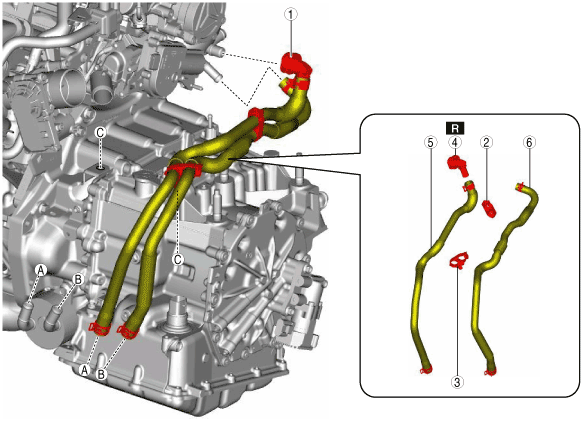
6. Remove in the order indicated in the table.
7. Install in the reverse order of removal.
8. Add the engine coolant. (See ENGINE COOLANT REPLACEMENT [SKYACTIV-G 1.3, SKYACTIV-G 1.5].)
adejjw00010833
|
|
1
|
Water hose component
|
|
2
|
Hose clip
|
|
3
|
Water hose No.1
|
|
4
|
Water hose No.2
|
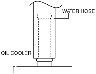
Water hose No.1 and No.2 (oil cooler side) installation note
1. Install the water hose to the oil cooler as shown in the figure with the hose clamp expanded.
am3uuw00008323
|
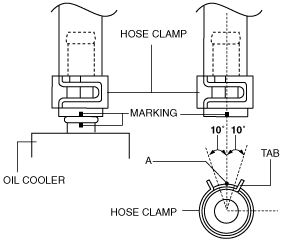
2. Install the hose clamp so that center A of the hose clamp tab is within the range shown in the figure.
am6zzw00009017
|
3. Verify that the hose clamp does not interfere with any other components.
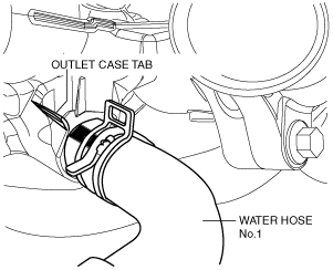
Water hose No.1 (outlet case side) installation note
1. Install the water hose No.1 to the outlet case as shown in the figure with the hose clamp expanded.
am2zzw00009859
|
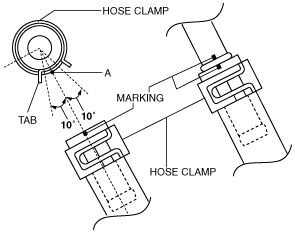
2. Install the hose clamp so that center A of the hose clamp tab is within the range shown in the figure.
am6zzw00009019
|
3. Verify that the hose clamp does not interfere with any other components.
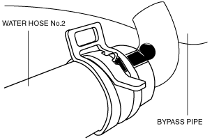
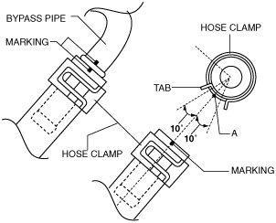
Water hose No.2 (bypass pipe side) installation note
1. Install the water hose No.2 to the bypass pipe as shown in the figure with the hose clamp expanded.
am2zzw00009860
|
2. Install the hose clamp so that center A of the hose clamp tab is within the range shown in the figure.
am6zzw00009021
|
3. Verify that the hose clamp does not interfere with any other components.
Water Hose (SKYACTIV-G 1.5 (With Coolant Control Valve))
1. Disconnect the negative battery cable. (See NEGATIVE BATTERY CABLE DISCONNECTION/CONNECTION.)
2. Remove the air cleaner and air hose as a single unit. (See INTAKE-AIR SYSTEM REMOVAL/INSTALLATION [SKYACTIV-G 1.3, SKYACTIV-G 1.5].)
3. Remove the battery tray and PCM component. (See BATTERY REMOVAL/INSTALLATION [SKYACTIV-G 1.3, SKYACTIV-G 1.5].)
4. Remove the front under cover No.2. (See FRONT UNDER COVER No.2 REMOVAL/INSTALLATION.)
5. Drain the engine coolant. (See ENGINE COOLANT REPLACEMENT [SKYACTIV-G 1.3, SKYACTIV-G 1.5].)
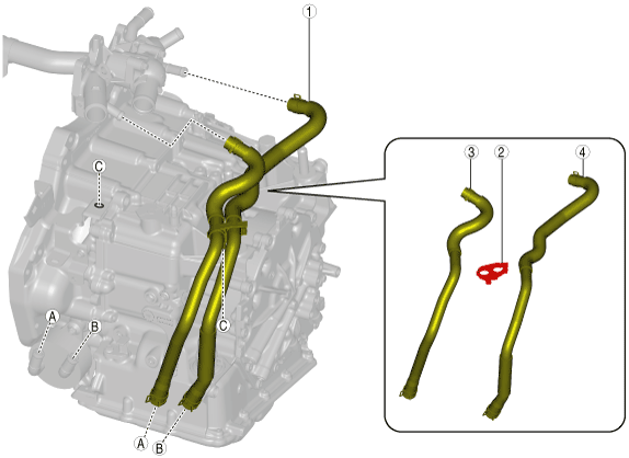
6. Remove in the order indicated in the table.
7. Install in the reverse order of removal.
8. Add the engine coolant. (See ENGINE COOLANT REPLACEMENT [SKYACTIV-G 1.3, SKYACTIV-G 1.5].)
am2zzw00014919
|
|
1
|
Water hose component
|
|
2
|
Hose clip No.1
|
|
3
|
Hose clip No.2
|
|
4
|
Quick release connector
|
|
5
|
Water hose No.1
|
|
6
|
Water hose No.2
|
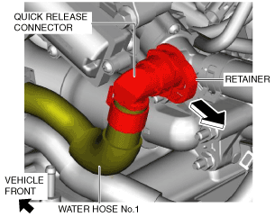
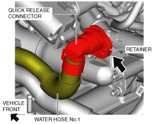
Water hose No.1 (coolant control valve side) removal note
1. Move the retainer in the direction of the arrow shown in the figure.
am2zzw00014920
|
2. Disconnect the quick release connector from the coolant control valve.
Water hose No.1 and No.2 (oil cooler side) installation note
1. Install the water hose to the oil cooler as shown in the figure with the hose clamp expanded.
am3uuw00008323
|
2. Install the hose clamp so that center A of the hose clamp tab is within the range shown in the figure.
am6zzw00009017
|
3. Verify that the hose clamp does not interfere with any other components.
Water hose No.1 (coolant control valve side) installation note
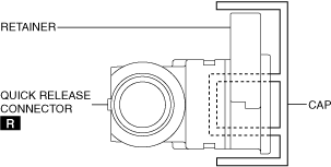
1. Remove the cap from a new quick release connector.
ac5wzw00010982
|
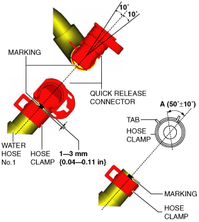
2. Install the quick release connector to water hose No.1 as shown in the figure with the hose clamp expanded.
am2zzw00014921
|
3. Install the hose clamp so that it is within area A shown in the figure.
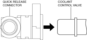
4. Press the quick release connector into the coolant control valve.
am2zzw00014922
|
5. Press in the retainer with your fingers in the direction of the arrow shown in the figure.
am2zzw00014923
|
6. Lightly pull and push the quick release connector a few times, and then verify that it is connected securely.
7. Verify that the hose clamp does not interfere with the surrounding accessories.
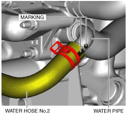
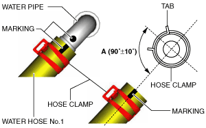
Water hose No.2 (water pipe side) installation note
1. Install water hose No.2 to the water pipe as shown in the figure with the hose clamp expanded.
am2zzw00014924
|
2. Install the hose clamp so that it is within area A shown in the figure.
am2zzw00014925
|
3. Verify that the hose clamp does not interfere with the surrounding accessories.
Oil Cooler
1. Disconnect the negative battery cable. (See NEGATIVE BATTERY CABLE DISCONNECTION/CONNECTION.)
2. Remove the front under cover No.2. (See FRONT UNDER COVER No.2 REMOVAL/INSTALLATION.)
3. Drain the ATF. (See AUTOMATIC TRANSAXLE FLUID (ATF) REPLACEMENT [CW6A-EL].)
4. Drain the engine coolant. (See ENGINE COOLANT REPLACEMENT [SKYACTIV-G 1.3, SKYACTIV-G 1.5].)
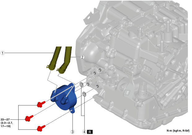
5. Remove in the order indicated in the table.
6. Install in the reverse order of removal.
7. Add the engine coolant. (See ENGINE COOLANT REPLACEMENT [SKYACTIV-G 1.3, SKYACTIV-G 1.5].)
8. Add the ATF. (See AUTOMATIC TRANSAXLE FLUID (ATF) REPLACEMENT [CW6A-EL].)
9. Perform the “Mechanical System Test”. (See MECHANICAL SYSTEM TEST [CW6A-EL].)
am2zzw00009378
|
|
1
|
Water hose No.1
|
|
2
|
Water hose No.2
|
|
3
|
Water-cooled oil cooler
|
|
4
|
O-rings
|
Water hose No.1 and No.2 (oil cooler side) installation note
1. Install the water hose to the oil cooler as shown in the figure with the hose clamp expanded.
am3uuw00008323
|
2. Install the hose clamp so that center A of the hose clamp tab is within the range shown in the figure.
am6zzw00009017
|
3. Verify that the hose clamp does not interfere with any other components.