 |
am2zzw00014938
STEERING GEAR AND LINKAGE ASSEMBLY
id061300802100
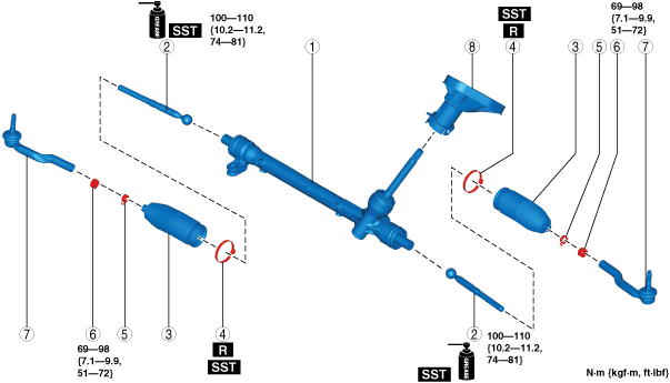
1. Assemble in the order shown in the figure.
2. Install the steering gear and linkage. (See STEERING GEAR AND LINKAGE REMOVAL/INSTALLATION.)
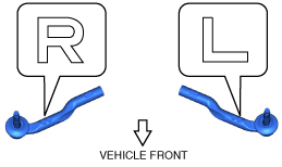
L.H.D.
am2zzw00014938
|
R.H.D.
am2zzw00014939
|
|
1
|
Steering gear
|
|
2
|
Tie Rod
(See Tie Rod Assembly Note.)
|
|
3
|
Boot
|
|
4
|
Boot band
(See Boot Band Assembly Note .)
|
|
5
|
Boot clamp
|
|
6
|
Locknut
|
|
7
|
Tie-rod end
(See Tie-rod End Assembly Note.)
|
|
8
|
Dust cover
|
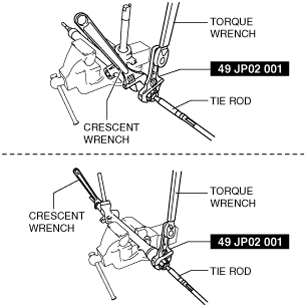
Tie Rod Assembly Note
1. Install the SST to the torque wrench as shown in the figure, set it on the tie rod, and measure dimensions A and L shown in the figure.
adejjw00015170
|
2. Tighten the tie rod after calculating the tightening torque using the following formula.
am2zzw00014872
|
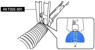
Boot Band Assembly Note
1. Assemble the boot band to the boot.
2. Crimp the boot band using the SST.
am2zzw00008168
|
3. Verify that the crimping clearance A is within the specification.
4. Rotate the by hand and verify that it is securely installed to the boot band.
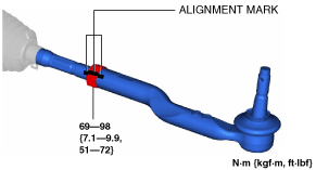
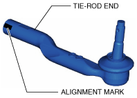
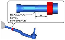
Tie-rod End Assembly Note
1. Align the marks that were made before removing the tie-rod end, and assemble the tie-rod end to the tie rod.
am2zzw00008139
|
am2zzw00008138
|
am2zzw00008726
|
2. Verify that dimension A shown in the figure is within the specification.
am2zzw00008141
|