 |
ac3wzn00000104
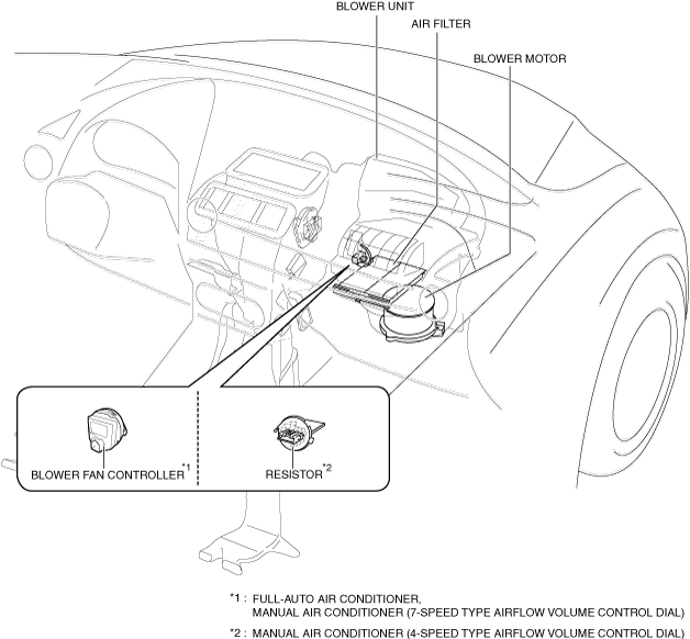
BLOWER SYSTEM
id071100001200
Outline
Function
Structural View
ac3wzn00000104
|
Operation
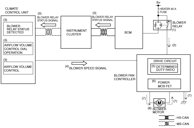
Full-auto air conditioner, manual air conditioner (7-speed type airflow volume control dial)
1. When the ignition is switched ON (engine off or on), the BCM turns the blower relay on (1).
2. When the blower relay turns on, the blower fan controller goes on operation standby (2).
3. When an operation request signal is detected (3) by the operation of the airflow volume control dial or the automatic control, the climate control unit sends (4) a blower speed signal to the blower fan controller.
4. The blower fan control driver circuit determines (5) the duty value to rotate the blower motor based on the blower speed signal and turns the power MOS FET on or off (6).
5. When the power MOS FET is turned on, the blower motor circuit is established (7) and the blower motor rotates (8).
6. The power MOS FET repeatedly turns on or off at high speed to control the blower motor and the rotation speed.
adejjn00002798
|
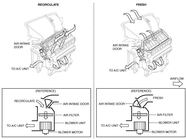
7. When the blower motor rotates, airflow is sent to the A/C unit. In addition, the air intake door is either at FRESH or RECIRCULATE depending on the air intake door position.
am2zzn00002097
|
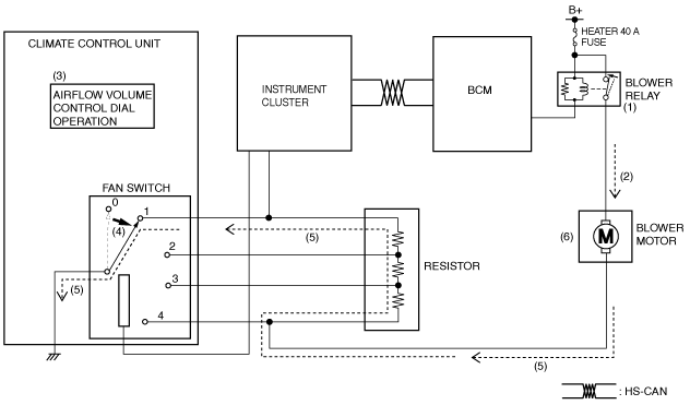
Manual air conditioner (4-speed type airflow volume control dial)
1. When the ignition is switched ON (engine off or on), the BCM turns on (1) the blower relay.
2. When the blower relay turns on, the blower motor goes on operation standby (2).
3. When the fan switch speed is switched (4) to 1 by the operation (3) of the airflow volume control dial of the climate control unit, a fan switch circuit is established (5) and the blower motor rotates (6).
4. The resister internal resistance decreases as the voltage applied to the blower motor by the fan switch increases in speed to 2, 3, and 4. Therefore, the blower motor rotation speed increases.
am2zzn00002098
|
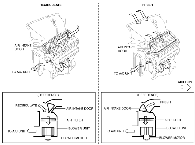
5. When the blower motor rotates, air is sent to the A/C unit. In addition, the air intake door is either at FRESH or RECIRCULATE depending on the air intake door position.
am2zzn00002099
|