 |
am2zzw00011264
THE HEADLIGHT AUTO LEVELING SYSTEM DOES NOT OPERATE IN RESPONSE TO VEHICLE POSTURE [HEADLIGHT AUTO LEVELING SYSTEM]
id0903d0013800
Description
Possible malfunction
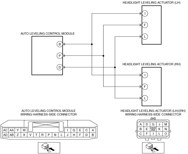
System wiring diagram
am2zzw00011264
|
Diagnostic Procedure
|
Step |
Inspection |
Action |
|
|---|---|---|---|
|
1
|
LEVELING OPERATION SIGNAL INSPECTION
• Using the M-MDS, perform the headlight leveling actuator operation check mode.
• Does the headlight leveling actuator operate normally?
|
Yes
|
Go to Step 7.
|
|
No
|
Go to the next step.
|
||
|
2
|
INSPECT LEVELING OPERATION SIGNAL CIRCUIT FOR OPEN CIRCUIT
• Inspect the wiring harness for continuity between the auto leveling control module and headlight leveling actuator on the side in which the auto leveling system does not operate.
• Is there continuity?
|
Yes
|
Go to the next step.
|
|
No
|
Refer to the wiring diagram and verify if there is a common connector between auto leveling control module terminal P and headlight leveling actuator (LH)/(RH) terminal F.
If there is a common connector:
• Inspect the common connector and terminals for corrosion, damage, or disconnection and the common wiring harnesses for an open circuit to determine the malfunctioning location.
• Repair or replace the malfunctioning location and go to Step 7.
If there is no common connector:
• Repair or replace the wiring harness which has an open circuit and go to Step 7.
|
||
|
3
|
INSPECT LEVELING OPERATION SIGNAL CIRCUIT FOR SHORT TO GROUND
• Inspect for continuity between the ground and the wiring harness between the auto leveling control module and headlight leveling actuator on the side in which the auto leveling system does not operate.
• Is there continuity?
|
Yes
|
Refer to the wiring diagram and verify if there is a common connector between auto leveling control module terminal P and headlight leveling actuator (LH)/(RH) terminal F.
If there is a common connector:
• Inspect the common connector and terminals for corrosion, damage, or disconnection and the common wiring harnesses for short to ground to determine the malfunctioning location.
• Repair or replace the malfunctioning location and go to Step 7.
If there is no common connector:
• Repair or replace the wiring harness which is shorted to ground and go to Step 7.
|
|
No
|
Go to the next step.
|
||
|
4
|
DETERMINE IF MALFUNCTION CAUSE IS HEADLIGHT LEVELING ACTUATOR OR AUTO LEVELING CONTROL MODULE
• Replace the front combination light in which the auto leveling system does not operate.
• Does the auto leveling system operate correctly?
|
Yes
|
Troubleshooting completed.
|
|
No
|
Replace the auto leveling control module and go to Step 7.
|
||
|
5
|
INSPECT WIRING HARNESS BETWEEN HEADLIGHT LEVELING ACTUATOR AND AUTO LEVELING CONTROL MODULE FOR OPEN CIRCUIT
• Inspect for continuity in the wiring harness between the following terminals:
• Is there continuity?
|
Yes
|
Go to the next step.
|
|
No
|
Refer to the wiring diagram and verify if there is a common connector between the following terminals.
• Auto leveling control module terminal B—Headlight leveling actuator (LH)/(RH) terminal I
• Auto leveling control module terminal P—Headlight leveling actuator (LH)/(RH) terminal F
• Auto leveling control module terminal D—Headlight leveling actuator (LH)/(RH) terminal L
If there is a common connector:
• Inspect the common connector and terminals for corrosion, damage, or disconnection and the common wiring harnesses for an open circuit to determine the malfunctioning location.
• Repair or replace the malfunctioning location and go to Step 7.
If there is no common connector:
• Repair or replace the wiring harness which has an open circuit and go to Step 7.
|
||
|
6
|
INSPECT WIRING HARNESS BETWEEN HEADLIGHT LEVELING ACTUATOR AND AUTO LEVELING CONTROL MODULE FOR SHORT TO GROUND
• Inspect for continuity between body ground and the following terminals.
• Is there continuity?
|
Yes
|
Refer to the wiring diagram and verify if there is a common connector between the following terminals.
• Auto leveling control module terminal B—Headlight leveling actuator (LH)/(RH) terminal I
• Auto leveling control module terminal P—Headlight leveling actuator (LH)/(RH) terminal F
• Auto leveling control module terminal D—Headlight leveling actuator (LH)/(RH) terminal L
If there is a common connector:
• Inspect the common connector and terminals for corrosion, damage, or disconnection and the common wiring harnesses for short to ground to determine the malfunctioning location.
• Repair or replace the malfunctioning location and go to Step 7.
If there is no common connector:
• Repair or replace the wiring harness which is shorted to ground and go to Step 7.
|
|
No
|
Go to the next step.
|
||
|
7
|
VERIFY IF MALFUNCTION CAUSE IS CORRECTED
• Switch the ignition to ACC or ON (engine off or on).
• Does the LED headlight warning light illumination turn off?
|
Yes
|
Troubleshooting completed. (explain the contents of the servicing to the customer)
|
|
No
|
Verify the malfunction symptom in the symptom troubleshooting chart and perform the other applicable malfunction diagnosis.
|
||