|
1
|
DETERMINE IF MALFUNCTION CAUSE IS DOOR LOCK
• Refer to “door lock does not operate” symptom troubleshooting and perform the inspection.
• Is the advanced keyless entry system operating normally?
|
Yes
|
Troubleshooting completed. (Explain the contents of the servicing to the customer.)
|
|
No
|
Go to the next step.
|
|
2
|
VERIFY IF MALFUNCTION CAUSE IS OPERATION OTHER THAN OPERATION PERMISSION CONDITION
• Verify the advanced keyless operation by operating each request switch and the liftgate opener switch with all the following conditions met.
-
― All doors and liftgate closed
― Ignition switched off
― Remote transmitter is within reception area (80 cm radius from driver's door, front passenger's door, and liftgate)
• Is the advanced keyless entry system operating normally?
|
Yes
|
System is normal. (Explain to customer about operation range of advanced keyless entry system)
|
|
No
|
Go to the next step.
|
|
3
|
VERIFY IF MALFUNCTION CAUSE IS EXTRINSIC NOISE
• Ask the customer malfunction condition.
• Does the malfunction occur at the specified place where extrinsic noise is received such as a TV tower, electric power station, or a broadcast station?
|
Yes
|
System is normal. (Explain the customer that operation cannot be performed caused by extrinsic noise.)
|
|
No
|
Go to the next step.
|
|
4
|
VERIFY MALFUNCTION SYMPTOM
• Does the liftgate open using the liftgate opener switch operation?
|
Yes
|
Go to Step 7.
|
|
No
|
Go to the next step.
|
|
5
|
DETERMINE IF MALFUNCTION CAUSE IS LIFTGATE OPENER SWITCH
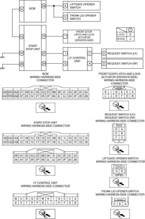
• Measure the voltage at BCM terminal 2S.
• Is the voltage normal?
Specification
-
Liftgate opener switch pressed: 1.0 V or less
Except above: 4.5 V
|
Yes
|
Go to Step 12.
|
|
No
|
Go to the next step.
|
|
6
|
INSPECT IF MALFUNCTION CAUSE IS OPEN CIRCUIT IN WIRING HARNESS BETWEEN BCM AND LIFTGATE OPENER SWITCH
• Disconnect the negative battery cable.
• Disconnect the BCM and liftgate opener switch connector.
• Inspect for continuity between the following terminals (vehicle wiring harness).
-
― Liftgate opener switch terminal A and BCM terminal 2S
• Is there continuity?
|
Yes
|
• Inspect the liftgate opener switch. If there is any malfunction, replace it.
• If the liftgate inspection is normal, inspect or repair the following:
-
― Liftgate latch and actuator
• After repair procedure, go to Step 12.
|
|
No
|
• Repair or replace the wiring harness for an open circuit.
• After repair procedure, go to Step 12.
|
|
7
|
VERIFY MALFUNCTION SYMPTOM
• Connect the negative battery cable.
• Verify the lock/unlock operation for all doors and liftgate using the request switch operation.
• Is door locked/unlocked?
|
Yes
|
Go to Step 12.
|
|
No
|
Go to the next step.
|
|
8
|
INSPECT IF MALFUNCTION CAUSE IS OPEN CIRCUIT IN WIRING HARNESS BETWEEN START STOP UNIT AND DOOR LOCK LINK SWITCH (DRIVER-SIDE)
• Disconnect the negative battery cable.
• Disconnect the start stop unit and the front door latch and lock actuator (driver's side) connector.
• Inspect for continuity between the following terminals (vehicle wiring harness).
-
― Start stop unit terminal 1P and front door lock link switch terminal D (L.H.D.)/J (R.H.D)
• Is there continuity?
|
Yes
|
Go to the next step.
|
|
No
|
• Repair or replace the wiring harness for an open circuit.
• After repair procedure, go to Step 12.
|
|
9
|
INSPECT IF MALFUNCTION CAUSE IS SHORT TO GROUND IN WIRING HARNESS BETWEEN START STOP UNIT AND DOOR LOCK LINK SWITCH (DRIVER-SIDE)
• Verify that the start stop unit connector is disconnected.
• Inspect for continuity between the following wiring harness terminals (vehicle wiring harness side) and body ground.
-
― Start stop unit terminal 1P and ground
• Is there continuity?
|
Yes
|
Go to the next step.
|
|
No
|
• Repair or replace the wiring harness for an open circuit.
• After repair procedure, go to Step 12.
|
|
10
|
INSPECT IF MALFUNCTION CAUSE IS OPEN CIRCUIT IN WIRING HARNESS BETWEEN START STOP UNIT AND GROUND
• Verify that the start stop unit connector is disconnected.
• Inspect for continuity between the following terminals (vehicle wiring harness).
-
― Start stop unit terminal 1AF and ground
― Start stop unit terminal 2B and ground
• Is there continuity?
|
Yes
|
Go to the next step.
|
|
No
|
• Repair or replace the wiring harness for an open circuit.
• After repair, go to Step 12.
|
|
11
|
INSPECT IF MALFUNCTION CAUSE IS OPEN CIRCUIT IN WIRING HARNESS BETWEEN REQUEST SWITCH AND LF CONTROL UNIT
• Disconnect the LF control unit and request switch connector.
• Inspect for continuity between the following terminals (vehicle wiring harness).
-
― Request switch (LF) terminal D and LF control unit terminal C
― Request switch (RF) terminal D and LF control unit terminal A
• Is there continuity?
|
Yes
|
Go to the next step.
|
|
No
|
• Repair or replace the wiring harness for an open circuit.
• After repair, go to the next step.
|
|
12
|
VERIFY IF MALFUNCTION CAUSE WAS CORRECTED
• Does the advanced keyless entry system operate normally?
|
Yes
|
Troubleshooting completed. (Explain the contents of the servicing to the customer.)
|
|
No
|
If the malfunction has not been resolved, repeat the inspection from Step 1.
|