OUTER MIRROR GLASS REMOVAL
id091200002800
R.H.D.
-
Note
-
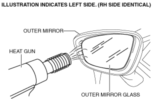
• Removal of the outer mirror glass can be facilitated by warming the back of the glass to approx. 50°C {90°F} to 60°{108°F} degrees using a heat gun.
• Be careful not to overheat the outer mirror, as temperatures higher than 60°C {108°F} degrees could deform it.
1. Disconnect the negative battery cable. (See NEGATIVE BATTERY CABLE DISCONNECTION/CONNECTION.)
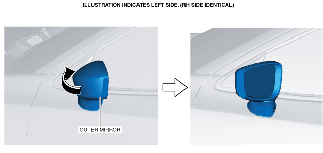
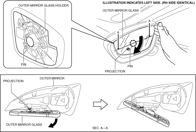
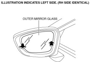
2. To facilitate removal of the outer mirror glass, orient the outer mirror in the direction of arrow shown in the figure.
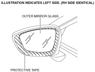
3. Affix the protective tape to the position shown in the figure to prevent scratches and damage.
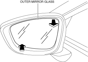
4. Move the outer mirror glass in the direction of arrow shown in the figure to secure a space for inserting your fingers.
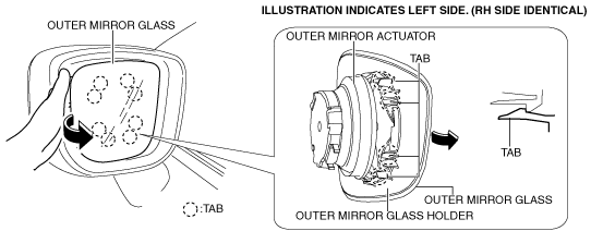
5. Insert your fingers into the location shown in the figure, move the outer mirror glass in the direction of arrow, and using the projection as the fulcrum point, disengage pin.
-
Caution
-
• When moving the outer mirror glass, if only the mirror glass is moved, the mirror glass could separate from the outer mirror glass holder. Move the outer mirror glass holder together with the mirror glass when moving the outer mirror glass.
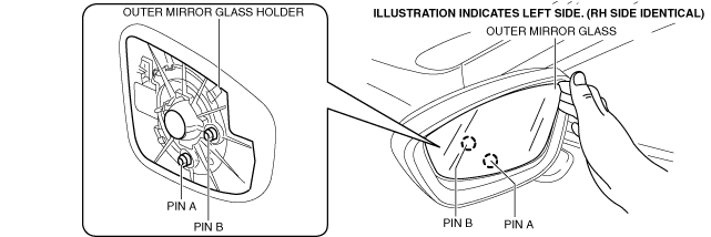
6. Insert your fingers behind the glass in the same manner as Step 5 and disengage the remaining pins A and B.
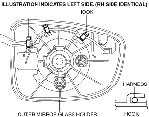
7. Remove the wiring harness for hooks.
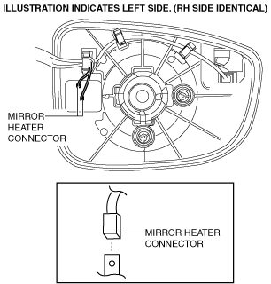
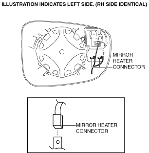
8. Disconnect the mirror heater connectors. (with heated outer mirror)
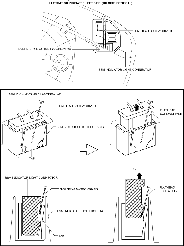
9. Insert a tape-wrapped flathead screwdriver to the position shown in the figure, remove the BSM indicator light connector. (with blind spot monitoring system)
-
Caution
-
• Remove the blind spot monitoring (BSM) indicator light connector being careful not to pry the blind spot monitoring (BSM) indicator light housing after inserting a tape-wrapped flathead screwdriver. If the BSM indicator light connector and the housing are damaged or deformed, poor contact of the connector may occur, causing the indicator light no to turn on.
10. Remove the mirror glass holder and the outer mirror glass as a single unit.
L.H.D.
-
Note
-
• Removal of the outer mirror glass can be facilitated by warming the back of the glass to approx. 50°C {90°F} to 60°{108°F} degrees using a heat gun.
• Be careful not to overheat the outer mirror, as temperatures higher than 60°C {108°F} degrees could deform it.
1. Disconnect the negative battery cable. (See NEGATIVE BATTERY CABLE DISCONNECTION/CONNECTION.)
2. To facilitate removal of the outer mirror glass, orient the outer mirror in the direction of the arrow shown in the figure.
3. Affix the protective tape to the position shown in the figure to prevent scratches and damage.
4. Move the outer mirror glass in the direction of the arrow shown in the figure to secure a space for inserting your fingers.
5. Insert your fingers into the location shown in the figure, move the outer mirror glass in the direction of the arrow, and disengage the outer glass from the outer mirror actuator.
-
Caution
-
• When detaching the outer mirror glass and the outer mirror actuator, the outer mirror glass could be damaged if the end of the outer mirror glass is moved by hand. When detaching the outer mirror glass, insert a hand into the engagement area of the outer mirror glass holder and the outer mirror actuator, and then move it.
6. Disconnect the mirror heater connectors. (with heated outer mirror)
7. Insert a tape-wrapped flathead screwdriver to the position shown in the figure, remove the BSM indicator light connector. (with blind spot monitoring system)
-
Caution
-
• The connector can be easily deformed, therefore do not apply excessive force.
8. Remove the mirror glass holder and the outer mirror glass as a single unit.