 |
am2zzn00004615
WINDSHIELD WIPER/WASHER SYSTEM
id091900001900
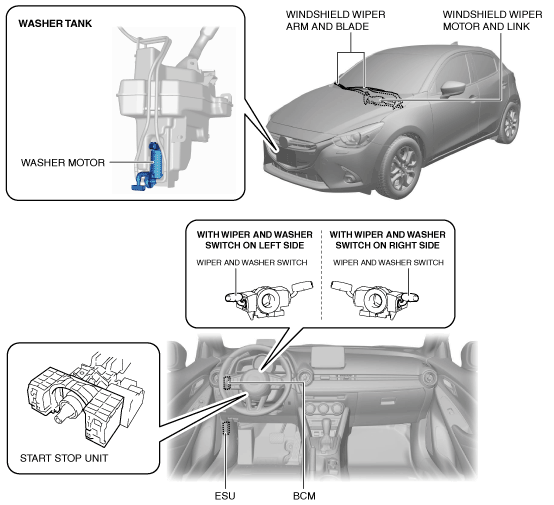
Outline
Structural View
am2zzn00004615
|
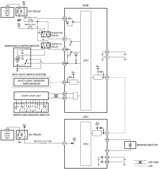
System Wiring Diagram
am2zzn00003920
|
Operation
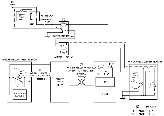
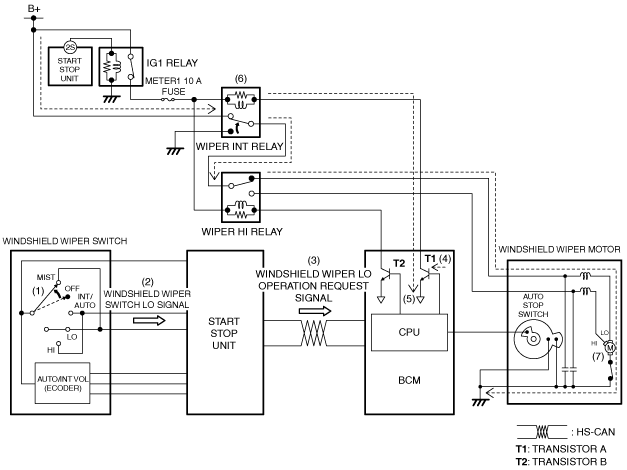
Continuous low operation
1. When the windshield wiper switch is in the LO position (1) with the ignition switched ON (engine off or on), the start stop unit detects (2) windshield wiper switch LO signal.
2. When the start stop unit detects the windshield wiper switch LO signal, the windshield wiper LO operation request signal is sent (3) to the BCM by CAN communication.
3. When the BCM receives the windshield wiper LO operation request signal, it turns transistor A on (4).
4. When transistor A turns on, a ground circuit with the wiper INT relay is established (5), and the wiper INT relay turns on (6).
5. When the wiper INT relay turns on, the windshield wipers operate continuously at low speed (7).
am2zzn00001924
|
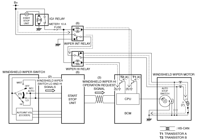
Continuous high operation
1. When the windshield wiper switch is in the HI position (1) with the ignition switched ON (engine off or on), the start stop unit detects (2) windshield wiper switch LO and HI signals.
2. When the start stop unit detects the windshield wiper switch LO and HI signals, the windshield wiper HI operation request signal is sent (3) to the BCM by CAN communication.
3. When the BCM receives the windshield wiper HI operation request signal, it turns transistors A and B on (4).
4. When transistors A and B turn on, a ground circuits with the wiper INT relay and the wiper HI relay are established (5), and the wiper INT relay and wiper HI relay turn on (6).
5. When the wiper INT relay and wiper HI relay turn on, the windshield wipers operate continuously at high speed (7).
am2zzn00001925
|
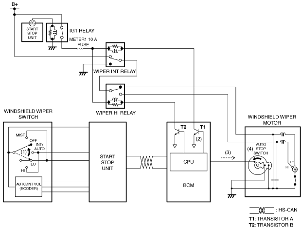
Auto-stop operation
1. When the windshield wiper switch is switched to the OFF position (1) during the windshield wiper operation, the BCM turns transistor A off (2).
2. When transistor A is turned off, current flows (3) to the auto stop switch which is on.
3. The windshield wipers operate to the park position by sending current to the auto stop switch.
4. When the windshield wipers return to the park position, the auto stop switch turns off (4).
am2zzn00003916
|
One-touch wiper operation
1. When the windshield wiper switch is in the MIST position (1) with the ignition switched ON (engine off or on), the start stop unit detects (2) windshield wiper switch LO signal.
2. When the start stop unit detects the windshield wiper switch LO signal, the windshield wiper LO operation request signal is sent (3) to the BCM by CAN communication.
3. When the BCM receives the windshield wiper LO operation request signal, it turns transistor A on (4).
4. When transistor A turns on, a ground circuit with the wiper INT relay is established (5), and the wiper INT relay turns on (6).
5. When the wiper INT relay turns on, the windshield wipers operate at low speed (7).
am2zzn00001927
|
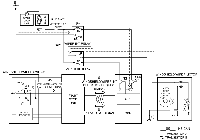
Intermittent wiper operation (Without auto wiper system)
1. When the windshield wiper switch is in the INT position (1) with the ignition switched ON (engine off or on), the start stop unit detects (2) windshield wiper switch INT signal.
2. When the start stop unit detects the windshield wiper switch INT signal, the windshield wiper INT operation request signal and the INT volume signal are sent (3) to the BCM by CAN communication.
3. When the BCM receives the windshield wiper INT operation request signal, it turns transistor A on (4).
4. When transistor A turns on, a ground circuit with the wiper INT relay is established (5), and the wiper INT relay turns on (6).
5. When the wiper INT relay turns on, the windshield wipers operate continuously at low speed (7).
6. When the windshield wipers stop at the park position due to the auto stop operation and after a certain period of time has elapsed, which was calculated based on the INT volume signal, the BCM operates the windshield wipers at a low speed (8). By repeating this, the windshield wipers operate intermittently.
am2zzn00001928
|
Auto wiper operation
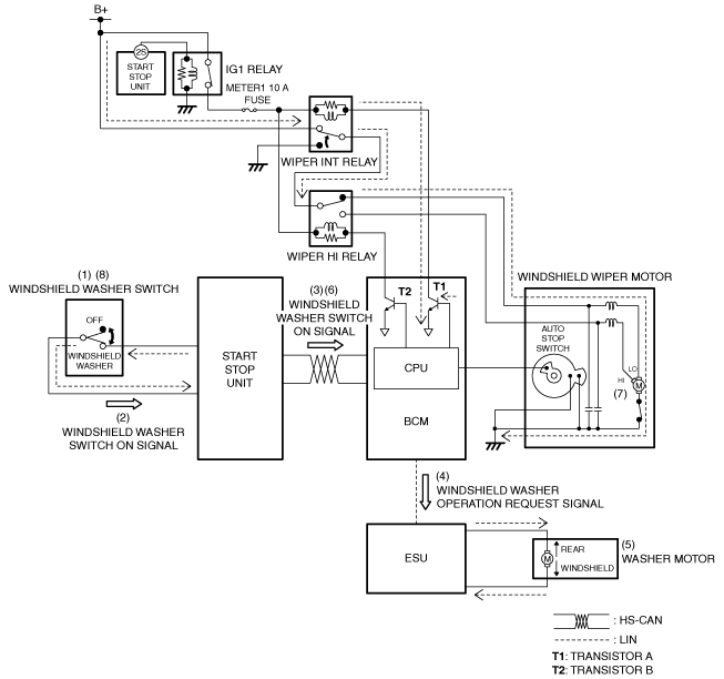
Synchronized washer operation
1. If the windshield washer switch is turned on (1) with the ignition switched ON (engine off or on) and the windshield wipers not operating, the start stop unit detects (2) a windshield washer switch on signal.
2. The start stop unit sends (3) the windshield washer switch on signal to the BCM via CAN communication.
3. When the BCM receives the windshield washer switch on signal, it sends (4) the windshield washer operation request signal to the electrical supply unit (ESU) via LIN communication.
4. When the electrical supply unit (ESU) receives the windshield washer operation request signal, the washer motor is driven (5) and washer fluid is sprayed from the windshield washer nozzles.
5. When the BCM receives (6) the windshield washer switch on signal for a certain period of time, it operates (7) the windshield wipers at low speed.
6. After the windshield washer switch is turned off (8), the windshield wipers operate 2 times at low speed and stop.
am2zzn00001929
|