 |
am2zzn00004616
REAR WIPER/WASHER SYSTEM
id091900002000
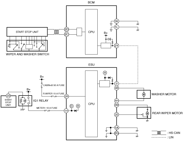
Outline
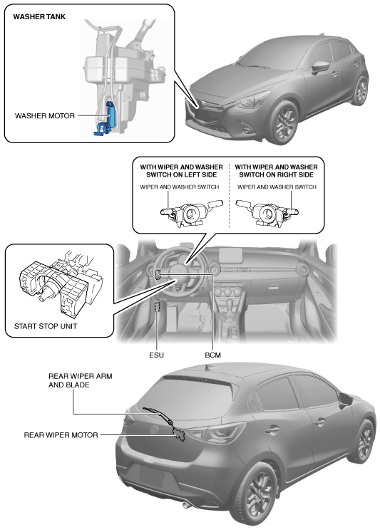
Structural View
am2zzn00004616
|
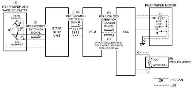
System Wiring Diagram
am2zzn00001931
|
Operation
Continuous operation
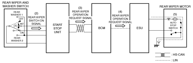
1. When the rear wiper and washer switch is in the ON position (1) with the ignition switched ON (engine off or on), the rear wiper switch ON signal is detected (2).
2. When the start stop unit detects the rear wiper switch ON signal, the rear wiper operation request signal is sent (3) to the BCM by CAN communication.
3. The BCM sends (4) the rear wiper operation request signal to the electrical supply unit (ESU) via LIN communication.
4. When the electrical supply unit (ESU) receives the rear wiper operation request signal, it operates (5) the rear wiper continuously.
am2zzn00001932
|
Auto-stop operation
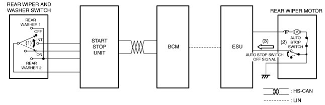
1. If the rear wiper and washer switch is switched to the OFF position (1) while the rear wiper is operating, the rear wiper is operated continuously because the auto stop switch is on.
2. The auto stop switch turns off (2) when the rear wiper operates to the park position.
3. If the auto stop switch off signal is detected (3), the electrical supply unit (ESU) stops the rear wiper motor.
am2zzn00001933
|
Intermittent wiper operation
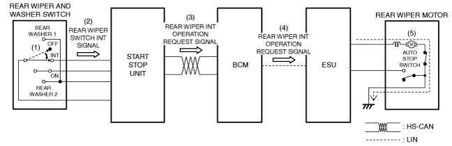
1. When the rear wiper and washer switch is in the INT position (1) with the ignition switched ON (engine off or on), the rear wiper switch INT signal is detected (2).
2. When the start stop unit detects the rear wiper switch INT signal, the rear wiper INT operation request signal is sent (3) to the BCM by CAN communication.
3. The BCM sends (4) the rear wiper INT operation request signal to the electrical supply unit (ESU) via LIN communication.
4. When the electrical supply unit (ESU) receives the rear wiper INT operation request signal, it operates (5) the rear wiper intermittently.
am2zzn00001934
|
Synchronized washer operation
1. When the rear wiper and washer switch is in the rear washer position (1) with the ignition switched ON (engine off or on), the rear washer switch on signal is detected (2).
2. The start stop unit sends (3) the rear washer switch on signal to the BCM via CAN communication.
3. When the BCM receives the rear washer switch on signal, it sends (4) the rear washer operation request signal to the electrical supply unit (ESU) via LIN communication.
4. When the electrical supply unit (ESU) receives the rear washer operation request signal, the washer motor is driven (5) and washer fluid is sprayed from the rear washer nozzle.
5. When the BCM receives (6) the rear washer switch on signal for a certain period of time, it sends (7) the synchronized washer rear wiper operation request signal to the electrical supply unit (ESU).
6. When the electrical supply unit (ESU) receives a synchronized washer rear wiper operation request signal, the rear wiper is operated (8) from the park position 2 times.
am2zzn00001935
|