MULTIPLEX COMMUNICATION SYSTEM
id100000001400
Outline
• A control area network (CAN) system has been adopted in which the multiple control modules send/receive signals using two common communication lines.
• Local CAN, ISO communication, or LIN communication has been adopted for the individual communication between control modules in consideration of the communication speed and the cost.
System Wiring Diagram
-
Note
-
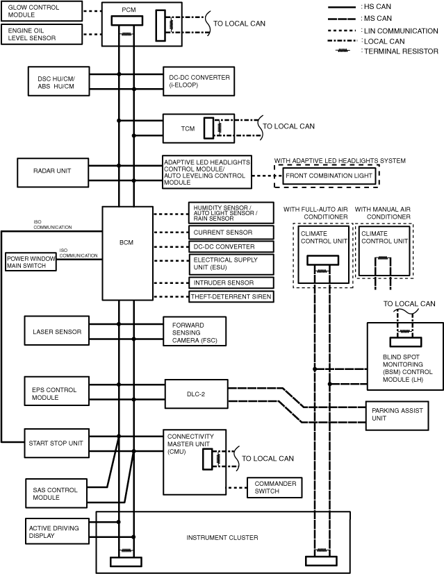
• The following figure shows the CAN/LIN communication/ISO communication/local CAN connection conditions. The availability of the equipment may differ depending on the vehicle specifications.
CAN/LIN communication/ISO communication/local CAN (L.H.D.)
CAN/LIN communication/ISO communication/local CAN (R.H.D.)
Local CAN
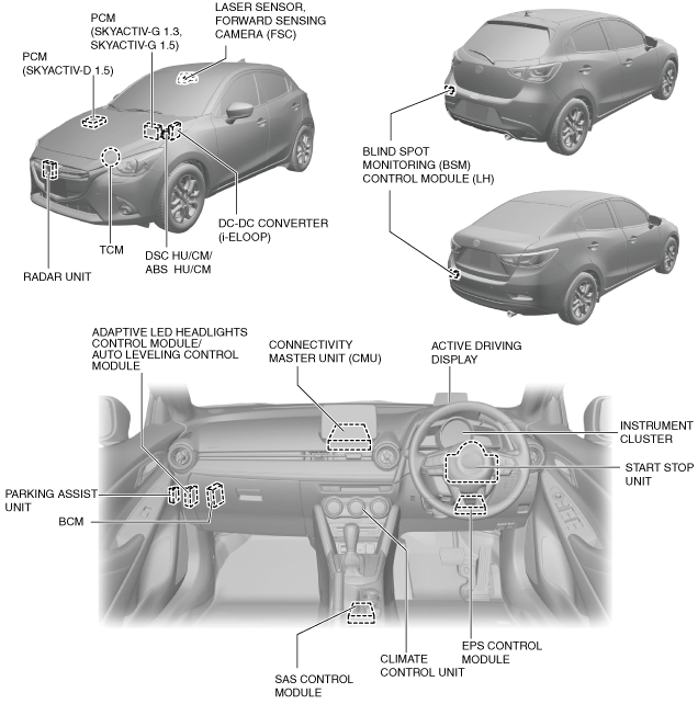
Structural view
-
Note
-
• The following figure shows the installation positions for the equipment which perform CAN communication. The availability of the equipment may differ depending on the vehicle specifications.
L.H.D.
R.H.D.
Function
CAN (controller area network) system
-
• HS-CAN (high-speed controller area network) is used for communication between the following modules:
-
― PCM
― DSC HU/CM (With DSC)
― ABS HU/CM (Without DSC)
― DC-DC converter (i-ELOOP) (With i-ELOOP)
― TCM (ATX)
― Adaptive LED headlights control module (With adaptive LED headlights)
― Auto leveling control module (With headlight auto leveling system)
― Radar unit (With smart brake support (SBS))
― BCM
― Laser sensor (With smart city brake support (SCBS))
― Forward sensing camera (FSC) (With forward sensing camera (FSC))
― EPS control module
― Start stop unit
― Connectivity master unit (CMU) (With center display)
― SAS control module
― Active driving display (With active driving display)
― Instrument cluster
• MS-CAN (mid-speed controller area network) is used for communication between the following modules:
-
― Instrument cluster
― Parking assist unit (With parking sensor system)
― Blind spot monitoring (BSM) control module (LH) (With blind spot monitoring (BSM) system)
― Climate control unit (Full-auto air conditioner)
― Climate control unit (Manual air conditioner)*1
*1 :The climate control unit for the vehicles equipped with the manual air conditioner system only uses the terminal resistance located on the substrate, therefore it does not use the CAN system.
Malfunction diagnosis procedure
-
• If a vehicle with a malfunction in a system controlled by a CAN system related module is brought in, verify the repair order form and the malfunctioning symptom first, then perform CAN malfunction diagnosis to determine if the malfunction cause is in the CAN system or not.
• For CAN malfunction diagnosis, the voltage at the CAN connection terminal on the DLC-2 is measured, and based on the measured value, the CAN circuit can be examined or the malfunction symptom can be determined.
• If the malfunction symptom is not an open circuit, inspect the voltage or continuity at the CAN circuit and determine the malfunctioning location.
• If the malfunction symptom is an open circuit, determine the area of the open circuit by using the displayed communication error DTC and the module in which communication has failed.
Ex.) Open circuit location determination procedure
1. Verify the CAN system-related module DTCs and the failed module using the Mazda Modular Diagnostic System (M-MDS).
|
DTC output module
|
Mazda Modular Diagnostic System (M-MDS) display
|
Output DTC
|
|
PCM
|
PCM
|
U0121:00
|
|
Radar unit
|
SBS/MRCC
|
U0121:00
|
|
TCM
|
TCM
|
U0121:00
|
|
Adaptive LED headlights control module
|
AFS/ALM
|
U0121:00
|
|
BCM
|
BCM
|
U0121:00
|
|
Laser sensor
|
SCBS
|
U0121:00
|
|
Forward sensing camera (FSC)
|
FSC
|
U0121:00
|
|
EPS control module
|
EPS
|
U0121:00
|
|
Start stop unit
|
SSU
|
U0121:00
|
|
U0121:87
|
|
Connectivity master unit (CMU)
|
CMU
|
U0121:00
|
|
Instrument cluster
|
IC
|
U0121:00
|
|
Module
|
Fail display
|
|
DSC HU/CM
|
×
|
2. As a result of DTC verification, only DTCs related to DSC HU/CM and communication errors are output and the DSC HU/CM is indicated as failed, therefore there could be a malfunction in the DSC HU/CM or in the wiring harness between connector C-26, C-27 and DSC HU/CM.
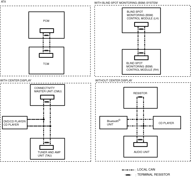
Local CAN
-
• Local CAN is used for communication between the following modules:
-
― Between PCM and TCM
― Between connectivity master unit (CMU), CD player/DVD/CD player, and tuner and amp unit (TAU)
― Between audio unit, Bluetooth® unit, and CD player
― Between blind spot monitoring (BSM) control module (LH) and blind spot monitoring (BSM) control module (RH)
LIN communication
-
• LIN communication is used for communication between the following modules:
-
― Between PCM and glow control module
― Between PCM and engine oil level sensor
― Between BCM and humidity sensor/auto light sensor/rain sensor
― Between BCM and DC-DC converter
― Between BCM and current sensor
― Between BCM and electrical supply unit (ESU)
― Between BCM and intruder sensor
― Between BCM and theft-deterrent siren
― Between adaptive LED headlights control module and front combination light (LH)
― Between adaptive LED headlights control module and front combination light (RH)
― Between connectivity master unit (CMU) and commander switch
ISO communication
-
• ISO communication is used for communication between the following modules:
-
― Between rear BCM and start stop unit
― Between rear BCM and power window main switch
Construction
CAN
-
• The HS-CAN has terminator resistors built into the following units which form the CAN lines.
-
― Between PCM terminals 2AK (CAN_H) and 2AL (CAN_L) (SKYACTIV-G 1.3, SKYACTIV-G 1.5 (Without coolant control valve))
― Between PCM terminals 2S (CAN_H) and 2T (CAN_L) (SKYACTIV-G 1.5 (With coolant control valve))
― Between PCM terminals 2C (CAN_H) and 2D (CAN_L) (SKYACTIV-D 1.5)
― Between instrument cluster terminals 1B (CAN_H) and 1D (CAN_L)
• The MS-CAN has terminal resistors built into the following units which form the CAN lines.
-
― Between instrument cluster terminals 1C (CAN_H) and 1E (CAN_L)
― Between climate control unit terminals B (CAN_H) and A (CAN_L) (Full-auto air conditioner)
― Between climate control unit terminals W (CAN_H) and X (CAN_L) (Manual air conditioner (RECIRCULATE/FRESH lever type))
― Between climate control unit terminals K (CAN_H) and L (CAN_L) (Manual air conditioner (RECIRCULATE/FRESH switch type))
Local CAN
-
• The local CAN has terminator resistors built into the following units which form the CAN lines.
-
― Between PCM terminals 1A (CAN_H) and 1B (CAN_L) (SKYACTIV-G 1.3, SKYACTIV-G 1.5)
― Between PCM terminals 1G (CAN_H) and 1C (CAN_L) (SKYACTIV-D 1.5)
― Between TCM terminals G (CAN_H) and H (CAN_L)
― Between connectivity master unit (CMU) terminals 2I (CAN_H) and 2J (CAN_L)
― Between tuner and amp unit (TAU) terminals 1AA (CAN_H) and 1AB (CAN_L)
― Between audio unit terminals 1O (CAN_H) and 1Q (CAN_L)
― Between CD player terminals G (CAN_H) and H (CAN_L) (Without center display)
― Between blind spot monitoring (BSM) control module (LH) terminals G (CAN_H) and J (CAN_L)
― Between blind spot monitoring (BSM) control module (RH) terminals G (CAN_H) and J (CAN_L)
LIN communication
-
• The LIN communication has drivers built into the following units which form the LIN communication lines.
-
― PCM (SKYACTIV-D 1.5)
― Glow control module
― Engine oil level sensor
― BCM
― Humidity sensor/auto light sensor/rain sensor
― Electrical supply unit (ESU)
― DC-DC converter
― Current sensor
― Intruder sensor
― Theft-deterrent siren
― Adaptive LED headlights control module
― Front combination light (LH)
― Front combination light (RH)
― Connectivity master unit (CMU)
― Commander switch
ISO communication
-
• The ISO communication has drivers built into the following units which form the ISO communication lines.
-
― BCM
― Start stop unit
― Power window main switch