GENERATOR INSPECTION [ZY]
id0117008003b0
-
Caution
-
• Do not apply voltage B directly to the generator D terminal, otherwise it could damage the internal parts of the generator (power transistor).
Generator Warning Light
1. Verify that the battery is fully charged.
2. Verify that the drive belt deflection/tension is within the specification. (See DRIVE BELT INSPECTION [ZY].)
3. Turn the ignition switch to the ON position and verify that the generator warning light illuminates.
-
• If the light does not illuminate, inspect the generator warning light, instrument cluster, and the PCM.
4. Verify that the generator warning light turns off after the engine is started.
-
• If the light does not turn off, inspect whether any of the following DTCs are displayed: P0112, P0113, P2502, P2503, P2504. (See ON-BOARD DIAGNOSTIC TEST [ZY].)
Generator
Voltage
1. Verify that the battery is fully charged.
2. Verify that the drive belt deflection/tension is within the specification. (See DRIVE BELT INSPECTION [ZY].)
3. Turn off all electrical loads.
4. Start the engine and verify that the generator rotates smoothly without any noise while the engine is running.
5. Measure the voltage at each terminals.
-
• If not within the specification, replace the generator.
Generator standard voltage (reference value) [IG-ON]
-
Terminal B: B+
-
Terminal P: Approx. 1 V or less
-
Terminal D: Approx. 0 V
Generator standard voltage (reference value) [Idle, 20 °C {68 °F}]
-
Terminal B: 13.0-15.0 V
-
Terminal P: Approx. 3.0-8.0 V
-
Terminal D: Turn the electrical loads (headlight, blower motor, rear window defroster) on and verify that the voltage reading increases.
Current
1. Verify that the battery is fully charged.
2. Verify that the drive belt deflection/tension is within the specification. (See DRIVE BELT INSPECTION [ZY].)
3. Disconnect the negative battery cable.
4. Connect a tester capable of reading 120 A or more between generator terminal B and the wiring harness.
5. Connect the negative battery cable.
6. Turn off all electrical loads.
7. Start the engine.
8. Start the engine and increase the engine speed to 2,000-2,500 rpm.
-
Note
-
• When the electrical load of the vehicle is low, specified current will not be verified although the generator is normal. In this case, increase the electrical load (by turning on the headlight and leave it for a while, then discharge the battery or by similar methods) and recheck.
-
• When the generator itself or the ambient temperature are too high, specified current will also not be verified. In this case, cool down the generator and recheck.
9. Turn the following electrical loads on and verify that the current reading increases.
-
• Headlight
-
• Blower motor
-
• Rear window defroster
-
- If it does not increase, replace the generator.
Generator generated current minimum value
-
70 % of the nominal output current (nominal output current: 90 A)
-
[ambient temp. 20 °C {68 °F}, voltage 13.0-15.0 V, both engine and generator are hot]
PCM and generator shearing inspection
1. Inspect as follows:
|
Step
|
Inspection
|
Action
|
|
1
|
Measure the generator terminal B voltage when the electrical loads*1 are on and off.
|
Above 15 V
|
Go to Step 2.
|
|
Between 13-15 V
|
Normal*2
|
|
Below 13 V
|
Go to Step 3.
|
|
2
|
Monitor the ALTTV PID using WDS or equivalent, or measure the voltage of PCM terminal 2AE using a tester. Is the voltage between 13-15 V ?
|
Yes
|
Go to Step 4.
|
|
No
|
PCM input error.
|
|
3
|
Monitor the ALTTV PID using WDS or equivalent, or measure the voltage of PCM terminal 2AE using a tester. Is the voltage between 13-15 V ?
|
Yes
|
Go to Step 5.
|
|
No
|
PCM input error.
|
|
4
|
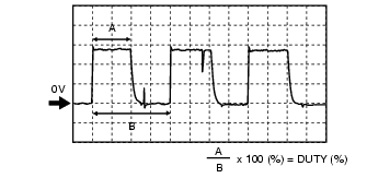
Monitor the ALTF PID using WDS or equivalent, or calculate the duty value of the PCM terminal 2AF using oscilloscope. Is the duty value 100 % ?
|
Yes
|
PCM input error.
|
|
No
|
PCM, generator, or both is not normal.
|
|
|
|
5
|
Monitor the ALTF PID using WDS or equivalent, or calculate the duty value of the PCM terminal 2AF using oscilloscope. Is the duty value 0 % ?
|
Yes
|
PCM input error.
|
|
No
|
PCM, generator, or both is not normal.
|
|
|
-
*1 :
Headlights, blower motor, rear window defroster, and stop lamp.
-
*2 :
If the generator field coil duty value does not change when electrical loads (headlights, blower motor, rear window defroster, stop lamp etc.) are on or off, inspection with discharged battery is needed.
Generator Inner Parts
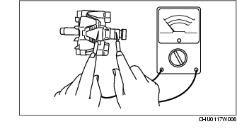
Rotor
1. Measure the resistance between the slip rings using an ohmmeter.
-
• If not as specified, replace the rotor.
Resistance [20 °C {68 °F}]
-
1.6-1.9 ohms
2. Verify that there is no continuity between the slip ring and core using an ohmmeter.
-
• If there is continuity, replace the rotor.
3. Inspect the slip ring surface condition.
-
• If the slip ring surface is rough, use a lathe or fine sandpaper to repair it.
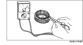
Stator coil
1. Inspect for continuity between the stator coil leads using an ohmmeter.
-
• If there is no continuity, replace the stator.
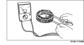
2. Verify that there is no continuity between the stator coil leads and the core using an ohmmeter.
-
• If there is continuity, replace the stator coil.
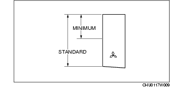
Brush
1. Inspect brushes for wear.
-
• If any brush is worn almost to or beyond the limit, replace all of the brushes.
Standard brush length
-
18.5 mm {0.73 in}
Minimum brush length
-
5.0 mm {0.2 in}
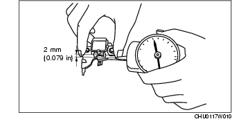
Brush spring
1. Measure the force of the brush spring using a spring pressure gauge.
2. Read the spring pressure gauge at the brush tip projection of 2 mm {0.079 in}.
-
• Replace the brush spring if necessary.
Standard spring force
-
4.8-6.0 N {0.49-0.61 kgf, 1.08-1.34 lbf}
Minimum spring force
-
2.16 N {0.22 kgf, 0.49 lbf}
Rectifier
1. Inspect for continuity of the diodes using an ohmmeter.
-
• If not as specified, replace the rectifier.
Specification
|
Tester
|
Continuity
|
|
Negative
|
Positive
|
|
E
|
P1, P2, P3
|
Yes
|
|
B
|
No
|
|
P1, P2, P3
|
E
|
No
|
|
B
|
Yes
|
Bearing
1. Inspect for abnormal noise, looseness, and sticking.
-
• Replace the bearing if necessary.