|
STEP
|
INSPECTION
|
ACTION
|
|
1
|
CONFIRM THE FOLLOWING PIDs USING WDS OR EQUIVALENT:
• ABS_MSG
• PCM_MSG
• Is "not present" massage displayed on WDS or equivalent?
|
Yes
|
Replace ABS CM.
|
|
No
|
Inspect instrument cluster.
If instrument cluster is normal, inspect CAN communication.
If instrument cluster malfunction, then go to next step.
|
|
2
|
VERIFY WHETHER MALFUNCTION IS IN WARNING LIGHTS AND INDICATOR LIGHT'S COMMON POWER SUPPLY, OR IN OTHER WARNING LIGHTS AND INDICATOR LIGHTS
• Do other warning and indicator lights illuminate when IG switch is turned ON?
|
Yes
|
Replace instrument cluster (open circuit in instrument cluster).
|
|
No
|
Go to next step.
|
|
3
|
INSPECT INSTRUMENT CLUSTER POWER SUPPLY FUSE
• Is instrument cluster ignition power supply fuse normal?
|
Yes
|
Go to next step.
|
|
No
|
Inspect for a short to ground on circuit of blown fuse.
Repair or replace as necessary.
Install appropriate amperage fuse.
|
|
4
|
VERIFY WHETHER MALFUNCTION IS IN WIRING HARNESS (BETWEEN INSTRUMENT CLUSTER POWER SUPPLY AND INSTRUMENT CLUSTER FOR CONTINUITY) OR INSTRUMENT CLUSTER
• Turn ignition switch ON.
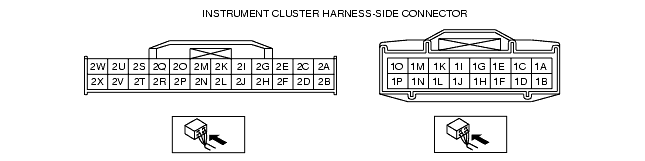
• Measure voltage at instrument cluster connector (24-pin) terminal 2V.
• Is voltage approx. 12V?
|
Yes
|
Replace instrument cluster (open circuit in instrument cluster).
|
|
No
|
Inspect for open circuit between instrument cluster and ground.
Repair or replace as necessary.
|
|
|