|
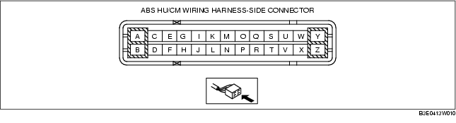
Terminal
|
Signal name
|
Connected to
|
Measured item
|
Measured terminal (measurement condition)
|
Standard
|
Inspection item(s)
|
|
A
|
-
|
-
|
-
|
-
|
-
|
-
|
|
B
|
Ground
(ABS motor)
|
Ground point
|
Continuity
|
B-ground point
|
Continuity detected
|
• Wiring harness
(B-ground point)
|
|
C
|
RR wheel-speed
(ground)
|
RR ABS wheel-speed sensor
|
Continuity
|
C-RR ABS wheel-speed sensor terminal C
|
Continuity detected
|
• Wiring harness (C-RR ABS wheel-speed sensor terminal C)
|
|
D
|
-
|
-
|
-
|
-
|
-
|
-
|
|
E
|
RR wheel-speed
(signal)
|
RR ABS wheel-speed sensor
|
Continuity
|
E-RR ABS wheel-speed sensor terminal A
|
Continuity detected
|
• Wiring harness (E-RR ABS wheel-speed sensor terminal A)
|
|
F
|
-
|
-
|
-
|
-
|
-
|
-
|
|
G
|
-
|
-
|
-
|
-
|
-
|
-
|
|
H
|
CAN_H
|
DLC-2
(CAN_H)
|
Continuity
|
H-DLC-2 terminal CAN_H
|
Continuity detected
|
• Wiring harness (H-DLC-2 terminal CAN_H)
|
|
I
|
LF wheel-speed
(signal)
|
LF ABS wheel-speed sensor
|
Continuity
|
I-LF ABS wheel-speed sensor terminal B
|
Continuity detected
|
• Wiring harness (I-LF ABS wheel-speed sensor terminal B)
|
|
J
|
-
|
-
|
-
|
-
|
-
|
-
|
|
K
|
LF wheel-speed
(ground)
|
LF ABS wheel-speed sensor
|
Continuity
|
K-LF ABS wheel-speed sensor terminal A
|
Continuity detected
|
• Wiring harness (K-LF ABS wheel-speed sensor terminal A)
|
|
L
|
CAN_L
|
DLC-2
(CAN_L)
|
Continuity
|
L-DLC-2 terminal CAN_L
|
Continuity detected
|
• Wiring harness (L-DLC-2 terminal CAN_L)
|
|
M
|
-
|
-
|
-
|
-
|
-
|
-
|
|
N
|
Power supply
(system)
|
Ignition switch
|
Voltage
|
The ignition switch is at the ON position.
|
B+
|
• Wiring harness
(N-ignition switch)
|
|
The ignition switch is off.
|
1 V or less
|
-
|
|
O
|
RF wheel-speed
(ground)
|
RF ABS wheel-speed sensor
|
Continuity
|
O-RF ABS wheel-speed sensor terminal A
|
Continuity detected
|
• Wiring harness (O-RF ABS wheel-speed sensor terminal A)
|
|
P
|
-
|
-
|
-
|
-
|
-
|
-
|
|
Q
|
RF wheel-speed
(signal)
|
RF ABS wheel-speed sensor
|
Continuity
|
Q-RF ABS wheel-speed sensor terminal B
|
Continuity detected
|
• Wiring harness (Q-RF ABS wheel-speed sensor terminal B)
|
|
R
|
KLN
|
DLC-2 (KLN)
|
Continuity
|
R-DLC-2 terminal KLN
|
Continuity detected
|
• Wiring harness (R-DLC-2 terminal KLN)
|
|
S
|
-
|
-
|
-
|
-
|
-
|
-
|
|
T
|
-
|
-
|
-
|
-
|
-
|
-
|
|
U
|
LR wheel-speed
(signal)
|
LR ABS wheel-speed sensor
|
Continuity
|
U-LR ABS wheel-speed sensor terminal B
|
Continuity detected
|
• Wiring harness (U-LR ABS wheel-speed sensor terminal B)
|
|
V
|
Brake switch
|
Brake switch
|
Voltage
|
V-Ground point
(When depressing the brake pedal with IG SW at the ON position)
|
VB
|
• Wiring harness (V-brake switch)
• Brake switch
|
|
V-Ground point
(When releasing the brake pedal with IG SW at the ON position)
|
1V or less
|
|
W
|
LR wheel-speed
(ground)
|
LR ABS wheel-speed sensor
|
Continuity
|
W-LR ABS wheel-speed sensor terminal D
|
Continuity detected
|
• Wiring harness (W-LR ABS wheel-speed sensor terminal D)
|
|
X
|
-
|
-
|
-
|
-
|
-
|
-
|
|
Y
|
Power supply
(solenoid operation)
|
Battery
|
Voltage
|
Under any condition
|
B+
|
• Wiring harness
(Y-battery)
|
|
Z
|
Power supply
(ABS motor operation)
|
Battery
|
Voltage
|
Under any condition
|
B+
|
• Wiring harness
(Z-battery)
|