ON-BOARD DIAGNOSTIC SYSTEM FUNCTION [ELECTRIC POWER STEERING (EPS)]
id0602001011a1
Malfunction Detection Function
• The malfunction detection function detects malfunctions in the input/output signal system of the EPS CM when the ignition switch is at the ON position or driving the vehicle.
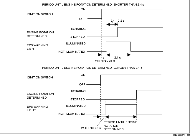
• When the ignition switch is turned to the ON position, the EPS warning light illuminates as shown in the diagram to inspect for open circuits in the light.
Malfunction Display Function
• When the malfunction detection function detects a malfunction, the EPS warning light illuminates to advise the driver. Using the external tester communication function, DTCs can be output to the DLC-2 via the CAN communication line. At the same time, malfunction detection results are sent to the memory and fail-safe functions.
Memory Function
• The memory function stores DTCs for malfunctions in input/output signal systems. With this function, once a DTC is stored it is not cleared after the ignition switch has been turned off (LOCK position), even if the malfunctioning signal system has returned to normal.
• Since the EPS CM has a built-in non-volatile memory, DTCs are not cleared even if the battery is removed. Therefore, it is necessary to clear the memory after performing repairs. Refer to the Workshop Manual for the DTC clearing procedure.
Fail-safe Function
• When the malfunction detection function determines a malfunction, the EPS warning light illuminates to advise the driver. At this time, the fail-safe function controls the system as shown in the DTC table.
DTC Table
|
System malfunction location
|
DTC (WDS or equivalent display)
|
Fail-safe function
|
|
EPS warning light illumination status
|
Control status
|
|
Battery power supply
|
B1317
|
Illuminated
|
Control suspended
|
|
Battery power supply
|
B1318
|
Illuminated
|
Control suspended
|
|
EPS CM (internal malfunction)
|
B1342
|
Illuminated
|
Control suspended
|
|
EPS CM (memory malfunction)
|
B2143
|
Not Illuminated
|
Control continues*2
|
|
Torque sensor
|
B2278
|
Illuminated
|
Control suspended
|
|
EPS CM configuration
|
B2477
|
Illuminated
|
Control suspended *1
|
|
EPS motor
|
C1099
|
Illuminated
|
Control suspended
|
|
CAN bus communication error
|
U0073
|
Not Illuminated
|
Control suspended *2
|
|
CAN bus communication error
|
U0100
|
Illuminated *3
|
Control suspended *4
|
|
CAN communication error
|
Engine speed signal error
|
U2023
|
Not Illuminated
|
Control suspended *5
|
|
Vehicle speed signal error
|
Illuminated *3
|
Control suspended *4
|
-
*1 :
The control is continued by the specified control program.
-
*2 :
The control is continued based on the last received engine speed and vehicle speed signal.
-
*3 :
Illuminates after switching to fail mode (controlled by assist torque to allow safe driving).
-
*4 :
Switches to fail mode (controlled by assist torque to allow safe driving) and continues control.
-
*5 :
The control is continued based on the last received engine speed signal.
Timing Chart Malfunction Contents
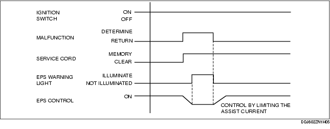
Service cord B1342, B2278, C1099
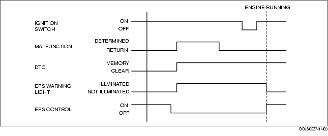
DTC B1317, B1318, B1342 (only for boost supply circuit inside EPS CM)

DTC U0100, U2023 (Only when there is a vehicle speed signal error)
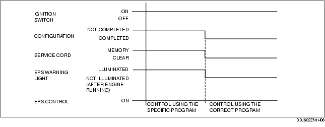
DTC B2477