ELECTRIC POWER STEERING CONTROL MODULE (EPS CM) CONSTRUCTION AND OPERATION


id061300248200

Construction

• The EPS CM is installed on the front passenger side in the cabin.
• The module calculates the proper assist current based on the steering force signal from the torque sensor installed on the steering gear and linkage, and the vehicle and engine speed signals from the PCM using CAN communication, and then outputs the control current to the EPS motor.

Function table

Control items

Function

Motor current control
• Calculates the proper assist current based on the steering force, and the vehicle and engine speeds, and outputs a target current to the EPS motor.
System overheating protection control
• In order to prevent system overheating, motor current is controlled according to turning limit control.
On-board diagnostic function
• Important parts of the system control have an on-board diagnostic function. In case a malfunction occurs, the EPS warning light illuminates to inform the driver and, at the same time, a DTC is stored in the EPS CM.
• When a malfunction is determined as a result of the on-board diagnosis, system control is suspended or limited to prevent any dangerous occurrence while driving.
Configuration function
• The configuration function according to the tire size has been adopted to optimize the steering characteristic.
Engine stall control
• If the engine is turned off while driving, the motor current is controlled until the ignition switch is turned off to ensure the steering force.

Operation

Motor current control

• The proper assist current is calculated based on the steering force signal from the torque sensor, and the vehicle speed signal from the PCM, and then the control current is output to the EPS motor.
• Also, various control corrections are performed according to the vehicle driving conditions.
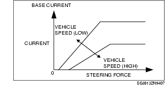
- Base current control
• The base current is the fundamental current amount for driving the EPS motor and is calculated based on the steering force and vehicle speed signals.

- Inertia correction control
• The inertia correction control compensates for the influence caused by motor revolution inertia (insufficient torque when starting, torque continuance when stopping). The correction current to the base current is increased according to vehicle conditions.
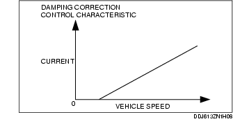
- Damping correction control
• The damping correction control reduces slight vibrations transmitted from the road surface (kickback) to the steering wheel using the motor control current. The correction current to the base current is either increased or decreased according to the vehicle conditions.

- Friction correction control
The friction correction control is calculated based on the estimated motor rotation speed of the EPS and vehicle speed signal.

• 

• The friction correction control compensates for friction during the EPS motor rotation. The correction current to the base current is increased according to vehicle conditions.

System overheating protection control

• The output current to the EPS is controlled to protect the EPS motor and EPS CM from a malfunction caused by overheating.
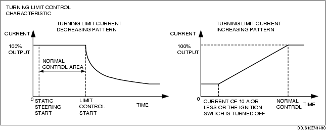
- Turning limit control
• - The turning limit gradually reduces current output to the EPS if the steering operation such as static steering is continued. If the turning limit is held, the turning limit control operates at a minimum of approx. 14 s.
• The motor current will gradually return to normal after low voltage motor current is detected (current of 10 A or less), such as during high-speed driving or when driving in a straight line, or when the ignition switch is turned off. A maximum of 40 min is required to return to normal conditions.
• If the turning limit control is operated, the EPS warning light does not illuminate and the DTC is not stored in the memory.