 |
am2zzw00006718
PROCEDURES FOR DETERMINING THE LOCATION OF A MALFUNCTION
id0902e6830500
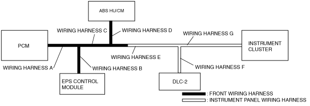
System Wiring Diagram
am2zzw00006718
|
PCM
1. Inspect the display of DTC U0101, U0121 and/or U0155 using the WDS or equivalent.
(See DTC TABLE [MULTIPLEX COMMUNICATION SYSTEM].)
2. Referring to the following table, determine the malfunctioning part of the CAN system.
|
Module |
Communication status |
Malfunction location |
|
|---|---|---|---|
|
ABS HU/CM |
Instrument cluster |
||
|
PCM
|
—
|
—
|
• Wiring harness A
• PCM
|
|
—
|
×
|
• Wiring harness D
• ABS HU/CM
|
|
|
—
|
×
|
• Wiring harness E
• Wiring harness G
• Instrument cluster
|
|
EPS Control Module
1. Inspect the display of DTC U0100 and/or U2023 using the WDS or equivalent.
(See DTC TABLE [MULTIPLEX COMMUNICATION SYSTEM].)
2. Referring to the following table, determine the malfunctioning part of the CAN system.
|
Module |
Communication status |
Malfunction location |
|---|---|---|
|
PCM |
||
|
EPS control module
|
—
|
• Wiring harness A
• Wiring harness B
• EPS control module
• PCM
|
ABS HU/CM
1. Inspect the display of DTC U2522 and/or U2523 using the WDS or equivalent.
(See DTC TABLE [MULTIPLEX COMMUNICATION SYSTEM].)
2. Referring to the following table, determine the malfunctioning part of the CAN system.
|
Module |
Communication status |
Malfunction location |
|
|---|---|---|---|
|
PCM |
Instrument cluster |
||
|
ABS HU/CM
|
—
|
—
|
• Wiring harness D
• ABS HU/CM
|
|
—
|
×
|
• Wiring harness A
• Wiring harness C
• PCM
|
|
|
×
|
—
|
• Wiring harness E
• Wiring harness G
• Instrument cluster
|
|
Instrument Cluster
1. Inspect the display of DTC U1900 using the WDS or equivalent.
(See DTC TABLE [MULTIPLEX COMMUNICATION SYSTEM].)
2. Access and monitor the “PCM_MSG” and “ABS_MSG” of PID using the WDS or equivalent.
3. Referring to the PID/DATA MONITOR TABLE, confirm the display status of the PID.
(See PID/DATA MONITOR TABLE [MULTIPLEX COMMUNICATION SYSTEM].)
4. Referring to the following table, determine the malfunctioning part of the CAN system.
|
Module |
Communication status |
Malfunction location |
|
|---|---|---|---|
|
PCM |
ABS HU/CM |
||
|
Instrument cluster
|
—
|
—
|
• Wiring harness E
• Wiring harness G
• Instrument cluster
|
|
—
|
×
|
• Wiring harness A
• Wiring harness C
• PCM
|
|
|
×
|
—
|
• Wiring harness D
• ABS HU/CM
|
|
Repair Procedure
1. Inspect the connector of malfunctioning module.
2. Inspect the malfunctioning wiring harnesses as follow:
3. Make sure to reconnect all disconnected connectors.
4. Clear the CAN system related DTCs using the WDS or equivalent.
5. Verify if the CAN system related DTCs are displayed using the WDS or equivalent.