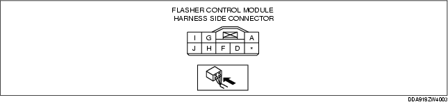
1. Remove the flasher control module with the connector connected.
2. Measure the voltage at each terminal (other than terminal F).
3. Disconnect the flasher control module connector.
4. Verify that continuity at terminal F is as indicated in the Terminal Voltage Table (Reference).
|
Terminal
|
Signal
|
Connected to
|
Test condition
|
Voltage (V)/Continuity
|
Inspection item(s)
|
|
|---|---|---|---|---|---|---|
|
A
|
Power supply
|
HAZARD 15 A fuse
|
Under any condition
|
B+
|
• HAZARD 15 A fuse
• Related wiring harness
|
|
|
D
|
Turn signal flasher (LH)
|
Turn light
(LH)
|
Turn switch (LH) is on.
|
Turn light (LH) flashes.
|
Alternates between 1.0 or less and B+
|
• Relay block
• Turn light (LH)
• Related wiring harness
|
|
Hazard warning switch is on.
|
||||||
|
Except above condition
|
1.0 or less
|
|||||
|
F
|
GND
|
Body GND
|
Under any condition: Inspect for continuity to ground.
|
Continuity
|
• GND
|
|
|
G
|
Turn signal flasher (RH)
|
Turn light
(RH)
|
Turn switch (RH) is on.
|
Turn light (RH) flashes.
|
Alternates between 1.0 or less and B+
|
• Relay block
• Turn light (RH)
• Related wiring harness
|
|
Hazard warning switch is on.
|
||||||
|
Except above condition
|
1.0 or less
|
|||||
|
H
|
Hazard warning switch on
|
Hazard warning switch
|
Hazard warning switch is on.
|
1.0 or less
|
• Hazard warning switch (See HAZARD WARNING SWITCH INSPECTION.)
• Related wiring harness
|
|
|
Hazard warning switch is off.
|
B+
|
|||||
|
I
|
Turn switch (RH) on/off
|
Turn switch
|
Turn the ignition switch to the ON position.
|
Turn switch (RH) is on.
|
B+
|
• Turn switch (See LIGHT SWITCH INSPECTION.)
• Related wiring harness
|
|
Except above condition
|
1.0 or less
|
|||||
|
J
|
Turn switch (LH) on/off
|
Turn switch
|
Turn the ignition switch to the ON position.
|
Turn switch (LH) is on.
|
B+
|
• Turn switch (See LIGHT SWITCH INSPECTION.)
• Related wiring harness
|
|
Except above condition
|
1.0 or less
|
|||||