 |
am2zzn00001372
ON-BOARD DIAGNOSTIC SYSTEM FUNCTION
id092000101800
Self-diagnostic Function
Malfunction detection function
Memory function
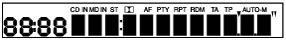
Display function
am2zzn00001372
|
|
Supplier code |
Supplier name |
|---|---|
|
01
|
SANYO Automedia
|
|
02
|
Panasonic
|
|
03
|
Clarion
|
|
04
|
Pioneer
|
|
Parts number |
Parts name |
|---|---|
|
00
|
Cassette deck
|
|
03
|
CD player
|
|
05
|
CD changer (external type)
|
|
06
|
CD changer
|
|
07
|
MD player
|
|
09
|
Base unit
|
|
10
|
MP3 applicable CD player
|
|
21
|
Center panel
|
|
Error code |
Malfunction description |
|---|---|
|
01
|
Internal mechanism error
|
|
02
|
Servo mechanism error
|
|
03
|
Mechanism stuck
|
|
04
|
Tape malfunction
|
|
07
|
Disc reading error
|
|
08
|
Blank media
|
|
10
|
BUS line (communication line) error
|
|
12
|
CAN line (communication line) error
|
|
17
|
Incorrect combination
|
|
18
|
Incorrect combination
|
|
19
|
Communication line
|
|
20
|
Insufficient power supply
|
|
22
|
Tuner error
|
|
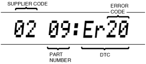
Screen display |
Malfunction location |
|
|---|---|---|
|
DTC |
Output signal |
|
|
00: Er01
|
—
|
Cassette deck
|
|
00: Er03
|
—
|
Cassette deck
|
|
00: Er04
|
CHECK TAPE
|
Cassette tape
|
|
00: Er10
|
—
|
Cassette deck communication circuit system
|
|
03: Er01
|
—
|
CD player
|
|
03: Er02
|
CHECK CD
|
CD player
|
|
03: Er07
|
CHECK CD
|
CD player
|
|
03: Er10
|
—
|
CD player communication circuit system
|
|
05: Er01
|
—
|
CD changer (external type) system
|
|
05: Er07
|
CHECK CD
|
CD changer (external type) system
|
|
05: Er10
|
—
|
CD changer (external type) communication circuit system
|
|
06: Er01
|
—
|
CD changer
|
|
06: Er02
|
CHECK CD
|
CD changer
|
|
06: Er07
|
CHECK CD
|
CD changer
|
|
06: Er10
|
—
|
CD changer communication circuit system
|
|
07: Er01
|
—
|
MD player
|
|
07: Er02
|
CHECK MD
|
MD player
|
|
07: Er07
|
CHECK MD
|
MD player
|
|
07: Er08
|
—
|
MD
|
|
07: Er10
|
—
|
MD player communication circuit system
|
|
09: Er20
|
—
|
Power supply circuit of base unit
|
|
09: Er22
|
—
|
Base unit (peripheral circuit for tuner)
|
|
10: Er01
|
—
|
MP3 applicable CD player
|
|
10: Er02
|
CHECK CD
|
MP3 applicable CD player
|
|
10: Er07
|
CHECK CD
|
MP3 applicable CD player
|
|
16: Er12
|
—
|
CAN system
|
|
21: Er17
|
—
|
Center panel system
|
|
21: Er18
|
—
|
Center panel system
|
|
21: Er19
|
—
|
Center panel system communication circuit system
|
|
no Err
|
—
|
No stored DTCs
|
Diagnostic Assist Function
LCD
am2zzn00001373
|
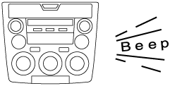
Switch
am2zzn00001374
|
Speaker
Radio
am2zzn00001375
|