|
Priority order of inspection
|
Ignition switch position
|
Check code
|
|---|---|---|
|
1
|
ON
|
22
|
|
2
|
01, 04, 08, 12, 13, 14, 16, 23, 25, 26, 59
|
|
|
3
|
LOCK
|
31
|
Diagnostic procedure
|
STEP
|
INSPECTION
|
INDICATION
|
ACTION
|
|---|---|---|---|
|
1
|
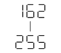
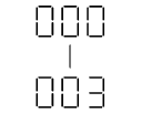
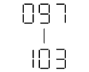
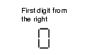
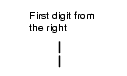
The three digits number is indicated after selecting check code 59. Confirm the first digit from the right.
|
|
The CAN system is okay.
Go to next step.
|
|
|
The DTC of CAN system is detected.
Perform the DTC inspection. (See DTC TABLE [MULTIPLEX COMMUNICATION SYSTEM])
• If the CAN system is okay, replace the instrument cluster.
Go to next step.
|
||
|
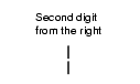
2
|
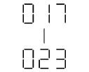
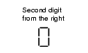
Confirm the second digit from the right.
|
|
The wiring harnesses between the fuel gauge sender unit and instrument cluster are okay.
Go to next step.
|
|
|
Inspect following parts.
• Fuel gauge sender unit
• Wiring harness (Fuel gauge sender unit-instrument cluster)
|
||
|
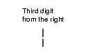
3
|
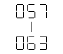
Confirm the third digit from the right.
|
|
The fuel pulse signal from the PCM is okay.
|
|
|
Inspect the PCM.
(See DTC TABLE [ZY], PCM INSPECTION [ZY].)
• If the PCM is okay, replace the instrument cluster.
|