 |
am2zzn00001550
ON-BOARD DIAGNOSTIC FUNCTION
id094000101700
Outline
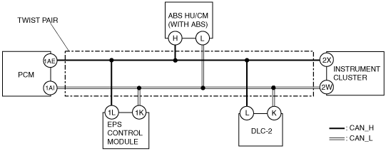
Block Diagram
am2zzn00001550
|
Failure detection function
Memory Function
Self-Malfunction Diagnostic Function
DTC table
|
DTC |
Malfunction location |
DTC output module |
|---|---|---|
|
U0073
|
CAN system communication error
|
• PCM
• EPS control module
|
|
U0100
|
Communication error to PCM
|
EPS control module
|
|
U0121
|
Communication error to ABS HU/CM
|
PCM
|
|
U0155
|
Communication error to instrument cluster
|
|
|
U1900
|
Communication error to the other module
|
Instrument cluster
|
|
U2012
|
CAN system communication error
|
ABS HU/CM (with ABS)
|
|
U2023
|
Abnormal message from PCM
|
EPS control module
|
|
U2516
|
CAN system communication error
|
Instrument cluster
|
|
U2522
|
Communication error between the PCM and ABS HU/CM (Powertrain-related signal)
|
ABS HU/CM (with ABS)
|
|
U2523
|
Communication error between the PCM and ABS HU/CM (Engine- related signal)
|
PID/Data Monitoring Function
|
PID name (definition) |
WDS display |
Detection state |
PID monitor module |
Terminal |
|---|---|---|---|---|
|
ABS_MSG
(Signal reception error from the ABS HU/CM)
|
Present
|
Circuit between the ABS HU/CM and monitor module is normal.
|
Instrument cluster
|
Instrument cluster:
2W, 2X
|
|
Not Present
|
Circuit between the ABS HU/CM and monitor module is abnormal.
|
|||
|
PCM_MSG
(Signal reception error from PCM)
|
Present
|
Circuit between the PCM and monitor module is normal.
|
||
|
Not Present
|
Circuit between the PCM and monitor module is abnormal.
|
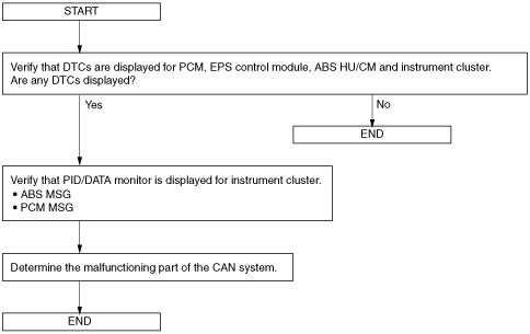
Narrowing Down Malfunction Locations
Flowchart
am2zzn00001551
|
Example (PCM-related communication error)
1. DTCs for the PCM, ABS HU/CM and instrument cluster can be verified using a WDS or equivalent.
|
Module |
Displayed DTC |
Probable malfunction location |
|---|---|---|
|
PCM
|
U0073
|
PCM-related CAN system malfunction
|
|
U0121
|
Communication error between PCM and ABS HU/CM
|
|
|
U0155
|
Communication error between PCM and instrument cluster
|
|
|
ABS HU/CM
|
U2523
|
Communication error between PCM and ABS HU/CM
|
|
Instrument cluster
|
U1900
|
Instrument cluster-related CAN system malfunction
|
2. PID/data monitor information for the instrument cluster can be verified using a WDS or equivalent.
|
Module |
PID name (definition) |
Condition |
Probable malfunction point |
|---|---|---|---|
|
Instrument cluster
|
PCM_MSG
(Missing message from the PCM)
|
Not Present
|
Communication error between instrument cluster and PCM
|
|
ABS_MSG
(Missing message from the ABS HU/CM)
|
Present
|
Normal communication between instrument cluster and ABS HU/CM
|
am2zzn00001552
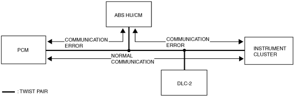
|
3. If there is a communication error between the ABS HU/CM and PCM, or between the instrument cluster and PCM, even if the communication between the ABS HU/CM and the instrument cluster is normal, it is probable that there is a malfunction in the PCM or PCM-related wiring harnesses.