|
e3e110zlct01
CYLINDER BLOCK (I) ASSEMBLY
id011000504000
1. Assemble in the order indicated in the table.
e3e110zlct01
|
|
1
|
Upper cylinder block
|
|
2
|
Oil jet valve
|
|
3
|
Upper main bearing
|
|
4
|
Crankshaft
|
|
5
|
Lower main bearing
|
|
6
|
Lower cylinder block
|
|
7
|
Connecting rod
|
|
8
|
Piston
(See Piston Assembly Note)
|
|
9
|
Piston pin
(See Piston Pin Assembly Note)
|
|
10
|
Piston ring
|
|
11
|
Piston, connecting rod
|
|
12
|
Upper connecting rod bearing
|
|
13
|
Lower connecting rod bearing
|
|
14
|
Connecting rod cap
|
Main Bearing Assembly Note
1. Assemble the upper and lower main bearing as specified shown in the figure.
ada2224e051
|
ada2224e050
|
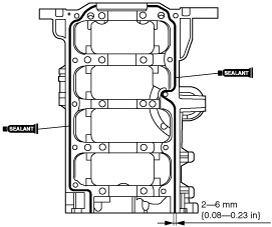
Lower Cylinder Block Assembly Note
1. Apply silicone sealant to the lower cylinder block attachment side as shown in the figure.
b3e0110e020
|
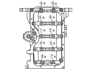
2. Apply clean engine oil to the lower cylinder block installation bolts A.
3. Tighten the lower cylinder block installation bolts A in two steps in the order shown in the figure.
b3e0110e006
|
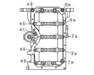
4. Tighten the lower cylinder block installation bolts B in the order shown in the figure.
b3e0110e007
|
5. Loosen bolts A and tighten the lower cylinder block installation bolts in two steps in the order shown a second time.
b3e0110e006
|
Piston Assembly Note
fde101ze3t02
|
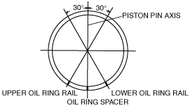
1. Position the end gap of each oil ring as shown in the figure.
ada2224e200
|
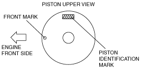
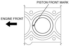
2. Insert the piston into the cylinder with the mark on top of the piston facing the front of the engine.
ada2224e250
|
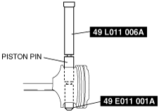
Piston Pin Assembly Note
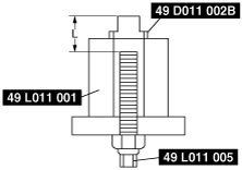
1. Assemble the SSTs as shown in the figure.
ada2224e316
|
2. Adjust the SSTs (stopper bolt) to the L length.
b3e0110e021
|
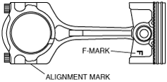
3. Point the end mark on the connecting rod and F- mark on the piston in the same direction as shown in the figure.
ada2224e252
|
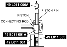
4. Insert the assembled piston pin and the SSTs into the piston and the connecting rod.
ada2224e122
|
5. Set the SSTs as shown in the figure.
ada2224e123
|
6. Press the piston pin into the piston and connecting rod until the SST (guide) contacts the SST (stopper bolt) using the hydraulic press. If it is less than the specification, replace the piston pin or the connecting rod.
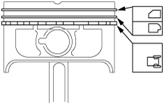
Piston Ring Assembly Note
1. Assemble the oil ring.
b3e0110ez106
|
2. Install the second ring with the notch facing downward.
3. Install the top ring with scraper face side upward.
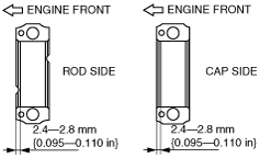
Connecting Rod Bearing Assembly Note
1. Install the connecting rod bearing to the connecting rod and the connecting rod cap as specified shown in the figure.
ada2224e095
|
Connecting Rod Cap Assembly Note
1. Install the connecting rod cap with the knock pins and the alignment marks aligned.
2. Tighten the connecting rod cap installation bolt in two steps.