 |
am2zzw00004047
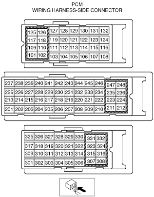
PCM INSPECTION [MZ-CD 1.6 (Y6)]
id0140b2802500
am2zzw00004047
|
PCM terminal voltage table (Reference)
|
Terminal |
Signal name |
Connected to |
Measurement condition |
Voltage (V) |
Inspection item(s) |
|
|---|---|---|---|---|---|---|
|
101
|
Fuel injector No.1 (high)
|
Fuel injector No.1
|
Inspect using the wave Profile. (See Inspection Using An Oscilloscope (Reference).)
|
• Related wiring harness
• Fuel injector No.1
|
||
|
102
|
Fuel injector No.4 (high)
|
Fuel injector No.4
|
Inspect using the wave Profile. (See Inspection Using An Oscilloscope (Reference).)
|
• Related wiring harness
• Fuel injector No.4
|
||
|
103
|
Fuel temperature sensor Ground
|
Fuel temperature sensor
|
Under any condition
|
Below 1.0
|
• Related wiring harness
• Fuel temperature sensor
|
|
|
104
|
Variable boost control signal
|
Variable boost control solenoid valve
|
Inspect using the wave Profile. (See Inspection Using An Oscilloscope (Reference).)
|
• Related wiring harness
• Variable boost control solenoid valve
|
||
|
105
|
—
|
|||||
|
106
|
—
|
|||||
|
107
|
—
|
|||||
|
108
|
Starter
|
Starter relay
|
Cranking
|
Below 1.0
|
• Related wiring harness
• Starter relay
|
|
|
109
|
Fuel injector No.3 (high)
|
Fuel injector No.3
|
Inspect using the wave Profile. (See Inspection Using An Oscilloscope (Reference).)
|
• Related wiring harness
• Fuel injector No.3
|
||
|
110
|
Fuel injector No.2 (high)
|
Fuel injector No.2
|
Inspect using the wave Profile. (See Inspection Using An Oscilloscope (Reference).)
|
• Related wiring harness
• Fuel injector No.2
|
||
|
111
|
—
|
|||||
|
112
|
—
|
|||||
|
113
|
Catalyst exhaust gas temperature sensor No.1 ground
|
Catalyst exhaust gas temperature sensor No.1
|
Under any condition
|
1.0 or less
|
• Catalyst exhaust gas temperature sensor
• Related wiring harness
|
|
|
114
|
Catalyst exhaust gas temperature sensor No.2 ground
|
Catalyst exhaust gas temperature sensor No.2
|
Under any condition
|
1.0 or less
|
• Catalyst exhaust gas temperature sensor
• Related wiring harness
|
|
|
115
|
—
|
|||||
|
116
|
—
|
|||||
|
117
|
Fuel injector No.4 (low)
|
Fuel injector No.4
|
Inspect using the wave Profile. (See Inspection Using An Oscilloscope (Reference).)
|
• Related wiring harness
• Fuel injector No.4
|
||
|
118
|
Fuel injector No.1 (low)
|
Fuel injector No.1
|
Inspect using the wave Profile. (See Inspection Using An Oscilloscope (Reference).)
|
• Related wiring harness
• Fuel injector No.1
|
||
|
119
|
Diesel particulate filter differential pressure sensor ground
|
Diesel particulate filter differential pressure sensor
|
Under any condition
|
1.0 or less
|
• Related wiring harness
• Fuel injector No.2
|
|
|
120
|
—
|
|||||
|
121
|
EGR valve position sensor ground
|
EGR valve
|
Switch the ignition ON
|
Below 1.0
|
• Diesel particulate filter differential pressure sensor
• Related wiring harness
|
|
|
122
|
—
|
|||||
|
123
|
Glow plug relay monitor
|
Glow plug relay
|
Switch the ignition ON
|
Approx. 1.3
|
• Related wiring harness
• Glow plug relay
|
|
|
Idle after warm-up
|
B+
|
|||||
|
124
|
MAF
|
MAF/IAT sensor
|
Inspect using the wave Profile. (See Inspection Using An Oscilloscope (Reference).)
|
• Related wiring harness
• MAF/IAT sensor
|
||
|
125
|
Fuel injector No.3 (low)
|
Fuel injector No.3
|
Inspect using the wave Profile. (See Inspection Using An Oscilloscope (Reference).)
|
• Related wiring harness
• Fuel injector No.3
|
||
|
126
|
Fuel injector No.2 (low)
|
Fuel injector No.2
|
Inspect using the wave Profile. (See Inspection Using An Oscilloscope (Reference).)
|
• Related wiring harness
• Fuel injector No.2
|
||
|
127
|
—
|
|||||
|
128
|
—
|
|||||
|
129
|
EGR valve position
|
EGR valve
|
Idle
|
Approx. 2.9
|
• Related wiring harness
• EGR valve
|
|
|
Switch the ignition ON
|
Approx. 0.9
|
|||||
|
130
|
—
|
|||||
|
131
|
—
|
|||||
|
132
|
Throttle valve position sensor signal
|
Throttle valve position sensor
|
Switch the ignition ON
|
Approx. 3.1
|
• Throttle valve position sensor
• Related wiring harness
|
|
|
Idle
|
Approx. 3.4
|
|||||
|
201
|
EGR valve position sensor supply
|
EGR valve
|
Switch the ignition ON
|
Approx. 5.0
|
• Related wiring harness
• EGR valve
|
|
|
202
|
Fuel pressure sensor supply
|
Fuel pressure sensor
|
Switch the ignition ON
|
Approx. 5.0
|
• Related wiring harness
• Fuel pressure sensor
|
|
|
203
|
Fuel pressure sensor ground
|
Fuel pressure sensor
|
Switch the ignition ON
|
Below 1.0
|
• Related wiring harness
• Fuel pressure sensor
|
|
|
204
|
MAP sensor ground
|
MAP sensor
|
Switch the ignition ON
|
Below 1.0
|
• Related wiring harness
• MAP sensor
|
|
|
205
|
MAP sensor supply
|
MAP sensor
|
Switch the ignition ON
|
Approx. 5.0
|
• Related wiring harness
• MAP sensor
|
|
|
206
|
CMP sensor supply
|
CMP sensor
|
Switch the ignition ON
|
Approx. 5.0
|
• Related wiring harness
• CMP sensor
|
|
|
207
|
Diesel particulate filter differential pressure sensor supply
|
Diesel particulate filter differential pressure sensor
|
Switch the ignition ON
|
Approx. 5.0
|
• Diesel particulate filter differential pressure sensor
• Related wiring harness
|
|
|
208
|
—
|
|||||
|
209
|
—
|
|||||
|
210
|
—
|
|||||
|
211
|
IAT sensor No.2 ground
|
IAT sensor No.2
|
Under any condition
|
Below 1.0
|
• Related wiring harness
• IAT sensor No.2
|
|
|
212
|
Fuel metering valve control signal
|
Fuel metering valve
|
Inspect using the wave Profile. (See Inspection Using An Oscilloscope (Reference).)
|
• Fuel metering valve
• Related wiring harness
|
||
|
213
|
—
|
|||||
|
214
|
—
|
|||||
|
215
|
—
|
|||||
|
216
|
—
|
|||||
|
217
|
—
|
|||||
|
218
|
CKP sensor supply
|
CKP sensor
|
Switch the ignition ON
|
Approx. 5.0
|
• Related wiring harness
• CKP sensor
|
|
|
219
|
Fuel pressure
|
Fuel pressure sensor
|
Switch the ignition off
|
Below 1.0
|
• Related wiring harness
• Fuel pressure sensor
|
|
|
Switch the ignition ON
|
Approx. 5.0
|
|||||
|
220
|
Catalyst exhaust gas temperature sensor No.2 signal
|
Catalyst exhaust gas temperature sensor No.2
|
Inspect using the M-MDS
|
• Catalyst exhaust gas temperature sensor
• Related wiring harness
|
||
|
221
|
Catalyst exhaust gas temperature sensor No.1 signal
|
Catalyst exhaust gas temperature sensor No.1
|
Inspect using the M-MDS
|
• Catalyst exhaust gas temperature sensor
• Related wiring harness
|
||
|
222
|
—
|
|||||
|
223
|
—
|
|||||
|
224
|
—
|
|||||
|
225
|
—
|
|||||
|
226
|
Oil pressure
|
Oil pressure switch
|
Switch the ignition ON
|
Below 1.0
|
• Related wiring harness
• Oil pressure switch
|
|
|
Idle
|
B+
|
|||||
|
227
|
EGR valve actuator
|
EGR valve
|
Inspect using the wave Profile. (See Inspection Using An Oscilloscope (Reference).)
|
• Related wiring harness
• EGR valve
|
||
|
228
|
EGR valve actuator
|
EGR valve
|
Under any condition
|
Below 1.0
|
• Related wiring harness
• EGR valve
|
|
|
229
|
MAF sensor ground
|
MAF sensor
|
Under any condition
|
Below 1.0
|
• Related wiring harness
• MAF sensor
|
|
|
230
|
ECT
|
ECT sensor
|
Engine coolant temperature:30°C {86°F}
|
Approx. 2.6
|
• Related wiring harness
• ECT sensor
|
|
|
Engine coolant temperature:70°C {158°F}
|
Approx. 1.1
|
|||||
|
231
|
IAT
|
MAF/IAT sensor
|
Switch the ignition ON
|
IAT 30 °C {86 °F}
|
Approx. 2.1
|
• Related wiring harness
• MAF/IAT sensor
|
|
IAT 60 °C {140 °F}
|
Approx. 1.1
|
|||||
|
232
|
Fuel temperature
|
Fuel temperature sensor
|
Fuel temperature:43°C {109.4°F}
|
Approx. 1.6
|
• Related wiring harness
• Fuel temperature sensor
|
|
|
Fuel temperature:47°C {116.6°F}
|
Approx. 1.3
|
|||||
|
233
|
—
|
|||||
|
234
|
MAP
|
MAP sensor
|
Switch the ignition ON
|
Approx. 2.4
|
• Related wiring harness
• MAP sensor
|
|
|
235
|
—
|
|||||
|
236
|
Power supply
|
Main relay
|
Switch the ignition ON
|
B+
|
• Related wiring harness
• Main relay
|
|
|
237
|
CMP sensor ground
|
CMP sensor
|
Under any condition
|
Below 1.0
|
• Related wiring harness
• CMP sensor
|
|
|
238
|
CKP
|
CKP sensor
|
Inspect using the wave Profile. (See Inspection Using An Oscilloscope (Reference).)
|
• Related wiring harness
• CKP sensor
|
||
|
239
|
CKP sensor ground
|
CKP sensor
|
Switch the ignition ON
|
Below 1.0
|
• Related wiring harness
• CKP sensor
|
|
|
240
|
CMP
|
CMP sensor
|
Inspect using the wave Profile. (See Inspection Using An Oscilloscope (Reference).)
|
• Related wiring harness
• CMP sensor
|
||
|
241
|
Main relay control
|
Main relay
|
Switch the ignition ON
|
Approx. 0.9
|
• Related wiring harness
• Main relay
|
|
|
242
|
IAT
|
IAT sensor No.2
|
Switch the ignition ON
|
IAT 30 °C {86 °F}
|
Approx. 3.5
|
• Related wiring harness
• IAT sensor No.2
|
|
243
|
—
|
|||||
|
244
|
ECT sensor ground
|
ECT sensor
|
Under any condition
|
Below 1.0
|
• Related wiring harness
• ECT sensor
|
|
|
245
|
—
|
|||||
|
246
|
Diesel particulate filter differential pressure sensor signal
|
Diesel particulate filter differential pressure sensor
|
Inspect using the M-MDS
|
• Diesel particulate filter differential pressure sensor
• Related wiring harness
|
||
|
247
|
Throttle valve actuator control signal
|
Throttle valve actuator
|
Switch the ignition ON
|
Approx. 0.6
|
• Throttle valve position sensor
• Related wiring harness
|
|
|
248
|
—
|
|||||
|
301
|
CAN_H
|
Controller area network (high)
|
Because this terminal is for CAN, determination by terminal voltage is not possible.
|
• Related wiring harness
|
||
|
302
|
—
|
|||||
|
303
|
—
|
|||||
|
304
|
Cooling fan relay No.3
|
Cooling fan relay No.3
|
Cooling fan relay No.3 operating
|
Below 1.0
|
• Related wiring harness
• Cooling fan relay No.3
|
|
|
Cooling fan relay No.3 not operating
|
B+
|
|||||
|
305
|
—
|
|||||
|
306
|
Refrigerant pressure sensor ground
|
Refrigerant pressure sensor
|
Under any condition
|
Below 1.0
|
• Related wiring harness
• Refrigerant pressure sensor
|
|
|
307
|
Ground
|
Body ground
|
Under any condition
|
Below 1.0
|
• Related wiring harness
|
|
|
308
|
Ground
|
Body ground
|
Under any condition
|
Below 1.0
|
• Related wiring harness
|
|
|
309
|
CAN_L
|
Controller area network (low)
|
Because this terminal is for CAN, determination by terminal voltage is not possible.
|
• Related wiring harness
|
||
|
310
|
APP
|
APP sensor
|
Accelerator pedal released
|
Approx. 3.3
|
• Related wiring harness
• APP sensor
|
|
|
Accelerator pedal depressed
|
Approx. 8.0
|
|||||
|
311
|
Ignition switch
|
Ignition switch
|
Switch the ignition ON
|
B+
|
• Related wiring harness
• Ignition switch
|
|
|
312
|
—
|
|||||
|
313
|
—
|
|||||
|
314
|
—
|
|||||
|
315
|
—
|
|||||
|
316
|
—
|
|||||
|
317
|
Brake
|
Brake switch
|
Brake pedal released
|
Below 1.0
|
• Related wiring harness
• Brake switch
|
|
|
Brake pedal depressed
|
B+
|
|||||
|
318
|
Cooling fan relay No.1
|
Cooling fan relay No.1
|
Cooling fan relay No.1 operating
|
Below 1.0
|
• Related wiring harness
• Cooling fan relay No.1
|
|
|
Cooling fan relay No.1 not operating
|
B+
|
|||||
|
319
|
—
|
|||||
|
320
|
Generator
|
Generator
|
Under any condition
|
Below 1.0
|
• Related wiring harness
• Generator
|
|
|
321
|
—
|
|||||
|
322
|
—
|
|||||
|
323
|
Refrigerant pressure sensor supply
|
Refrigerant pressure sensor
|
Switch the ignition ON
|
Approx. 5.0
|
• Related wiring harness
• Refrigerant pressure sensor
|
|
|
324
|
Refrigerant pressure
|
Refrigerant pressure sensor
|
Switch the ignition ON
|
Approx. 1.5
|
• Related wiring harness
• Refrigerant pressure sensor
|
|
|
325
|
—
|
|||||
|
326
|
Glow plug relay
|
Glow plug relay
|
Glow plug relay operating
|
Below 1.0
|
• Related wiring harness
• Glow plug relay
|
|
|
Glow plug relay not operating
|
B+
|
|||||
|
327
|
—
|
|||||
|
328
|
—
|
|||||
|
329
|
—
|
|||||
|
330
|
A/C relay
|
A/C relay
|
Idle
|
Refrigerant pressure switch on
|
Below 1.0
|
• Related wiring harness
• A/C relay
|
|
Refrigerant pressure switch off
|
B+
|
|||||
|
331
|
Power supply
|
Main relay
|
Switch the ignition ON
|
B+
|
• Related wiring harness
• Main relay
|
|
|
332
|
Ground
|
Body ground
|
Under any condition
|
Below 1.0
|
• Related wiring harness
|
|
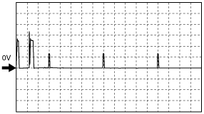
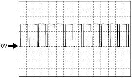
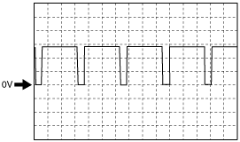
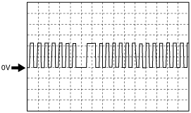
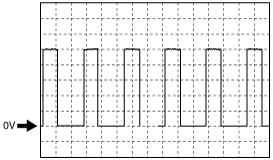
Inspection Using An Oscilloscope (Reference)
Fuel injector (+) signal
am2zzw00003096
|
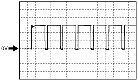
Variable boost control signal
am2zzw00004052
|
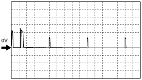
Fuel injector (-) signal
am2zzw00003097
|
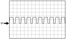
MAF sensor signal
am2zzw00004051
|
Fuel metering valve signal
am2zzw00004053
|
EGR valve actuator signal
am2zzw00002952
|
CKP sensor signal
am2zzw00002951
|
CMP sensor signal
am2zzw00002954
|