 |
am2zzw00002956
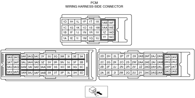
PCM INSPECTION [MZ-CD 1.4 DI Turbo]
id0140b8802500
Not Using the M-MDS
am2zzw00002956
|
PCM terminal voltage table (Reference)
|
Terminal |
Signal name |
Connected to |
Measurement condition |
Voltage (V) |
Inspection item(s) |
|
|---|---|---|---|---|---|---|
|
1A
|
CAN_H
|
Controller area network (high)
|
Because this terminal is for CAN, determination by terminal voltage is not possible.
|
• Related wiring harness
|
||
|
1B
|
CAN_L
|
Controller area network (low)
|
Because this terminal is for CAN, determination by terminal voltage is not possible.
|
• Related wiring harness
|
||
|
1C
|
ECT
|
ECT sensor
|
Engine coolant temperature:30°C {86°F}
|
Approx. 2.6
|
• Related wiring harness
• ECT sensor
|
|
|
Engine coolant temperature:70°C {158°F}
|
Approx. 1.1
|
|||||
|
1D
|
—
|
—
|
—
|
—
|
—
|
—
|
|
1E
|
ECT sensor ground
|
ECT sensor
|
Under any condition
|
Below 1.0
|
• Related wiring harness
• ECT sensor
|
|
|
1F
|
MAF sensor ground
|
MAF sensor
|
Under any condition
|
Below 1.0
|
• Related wiring harness
• MAF sensor
|
|
|
1G
|
IAT
|
IAT sensor No.2
|
Ignition switch on
|
IAT 30 °C {86 °F}
|
Approx. 1.9
|
• Related wiring harness
• IAT sensor No.2
|
|
IAT 40 °C {104 °F}
|
Approx. 1.4
|
|||||
|
1H
|
—
|
—
|
—
|
—
|
—
|
—
|
|
1I
|
MAF
|
MAF/IAT sensor
|
Inspect using the wave Profile.
|
• Related wiring harness
• MAF/IAT sensor
|
||
|
1J
|
Ignition switch
|
Ignition switch
|
Ignition switch on
|
B+
|
||
|
1K
|
Cooling fan relay No.3
|
Cooling fan relay No.3
|
Cooling fan relay No.3 operating
|
Below 1.0
|
• Related wiring harness
• Cooling fan relay No.3
|
|
|
Cooling fan relay No.3 not operating
|
B+
|
|||||
|
1L
|
Main relay control
|
Main relay
|
Ignition switch on
|
Approx. 0.9
|
• Related wiring harness
• Main relay
|
|
|
1M
|
—
|
—
|
—
|
—
|
—
|
—
|
|
1N
|
IAT sensor No.2 ground
|
IAT sensor No.2
|
Under any condition
|
Below 1.0
|
• Related wiring harness
• IAT sensor No.2
|
|
|
1O
|
Glow plug relay
|
Glow plug relay
|
Glow plug relay operating
|
Below 1.0
|
• Related wiring harness
• Glow plug relay
|
|
|
Glow plug relay not operating
|
B+
|
|||||
|
1P
|
—
|
—
|
—
|
—
|
—
|
—
|
|
1Q
|
—
|
—
|
—
|
—
|
—
|
—
|
|
1R
|
—
|
—
|
—
|
—
|
—
|
—
|
|
1S
|
Cooling fan relay No.1
|
Cooling fan relay No.1
|
Cooling fan relay No.1 operating
|
Below 1.0
|
• Related wiring harness
• Cooling fan relay No.1
|
|
|
Cooling fan relay No.1 not operating
|
B+
|
|||||
|
1T
|
—
|
—
|
—
|
—
|
—
|
—
|
|
1U
|
—
|
—
|
—
|
—
|
—
|
—
|
|
1V
|
—
|
—
|
—
|
—
|
—
|
—
|
|
1W
|
A/C relay
|
A/C relay
|
Idle
|
Refrigerant pressure switch on
|
Below 1.0
|
• Related wiring harness
• A/C relay
|
|
Refrigerant pressure switch off
|
B+
|
|||||
|
1X
|
—
|
—
|
—
|
—
|
—
|
—
|
|
1Y
|
Ground
|
Body ground
|
Under any condition
|
Below 1.0
|
• Related wiring harness
|
|
|
1Z
|
—
|
—
|
—
|
—
|
—
|
—
|
|
1AA
|
Fuel pressure ragulator
|
Fuel pressure ragulator
|
Inspect using the wave Profile.
|
• Related wiring harness
• Fuel pressure ragulator
|
||
|
1AB
|
Fuel metering valve
|
Fuel metering valve
|
Inspect using the wave Profile.
|
• Related wiring harness
• Fuel metering valve
|
||
|
1AC
|
Ground
|
Body ground
|
Under any condition
|
Below 1.0
|
• Related wiring harness
|
|
|
1AD
|
—
|
—
|
—
|
—
|
—
|
—
|
|
1AE
|
—
|
—
|
—
|
—
|
—
|
—
|
|
1AF
|
—
|
—
|
—
|
—
|
—
|
—
|
|
2A
|
—
|
—
|
—
|
—
|
—
|
—
|
|
2B
|
—
|
—
|
—
|
—
|
—
|
—
|
|
2C
|
—
|
—
|
—
|
—
|
—
|
—
|
|
2D
|
—
|
—
|
—
|
—
|
—
|
—
|
|
2E
|
—
|
—
|
—
|
—
|
—
|
—
|
|
2F
|
—
|
—
|
—
|
—
|
—
|
—
|
|
2G
|
—
|
—
|
—
|
—
|
—
|
—
|
|
2H
|
—
|
—
|
—
|
—
|
—
|
—
|
|
2I
|
MAP sensor supply
|
MAP sensor
|
Ignition switch on
|
Approx. 5
|
• Related wiring harness
• MAP sensor
|
|
|
2J
|
—
|
—
|
—
|
—
|
—
|
—
|
|
2K
|
CKP sensor ground
|
CKP sensor
|
Ignition switch on
|
Below 1.0
|
• Related wiring harness
• CKP sensor
|
|
|
2L
|
CKP
|
CKP sensor
|
Inspect using the wave Profile.
|
• Related wiring harness
• CKP sensor
|
||
|
2M
|
EGR valve position sensor supply
|
EGR valve position sensor
|
Ignition switch on
|
Approx. 5
|
• Related wiring harness
• EGR valve position sensor
|
|
|
2N
|
EGR valve position sensor ground
|
EGR valve
|
Ignition switch on
|
Below 1.0
|
• Related wiring harness
• EGR valve
|
|
|
2O
|
EGR valve position
|
EGR valve
|
Idle
|
Approx. 2.5
|
||
|
Ignition switch on
|
Approx. 0.9
|
|||||
|
2P
|
—
|
—
|
—
|
—
|
—
|
—
|
|
2Q
|
Fuel pressure sensor supply
|
Fuel pressure sensor
|
Ignition switch on
|
Approx. 5
|
• Related wiring harness
• Fuel pressure sensor
|
|
|
2R
|
Fuel pressure sensor ground
|
Fuel pressure sensor
|
Ignition switch on
|
Below 1.0
|
• Related wiring harness
• Fuel pressure sensor
|
|
|
2S
|
MAP
|
MAP sensor
|
Ignition switch on
|
Approx. 2.4
|
• Related wiring harness
• MAP sensor
|
|
|
2T
|
Fuel pressure
|
Fuel pressure sensor
|
Idle
|
Approx. 1.0
|
• Related wiring harness
• Fuel pressure sensor
|
|
|
Ignition switch on
|
Approx. 0.5
|
|||||
|
2U
|
—
|
—
|
—
|
—
|
—
|
—
|
|
2V
|
—
|
—
|
—
|
—
|
—
|
—
|
|
2W
|
MAP sensor ground
|
MAP sensor
|
Ignition switch on
|
Below 1.0
|
• Related wiring harness
• MAP sensor
|
|
|
2X
|
IAT
|
MAF/IAT sensor
|
Ignition switch on
|
IAT 30 °C {86 °F}
|
Approx. 1.9
|
• Related wiring harness
• MAF/IAT sensor
|
|
IAT 40 °C {104 °F}
|
Approx. 1.4
|
|||||
|
2Y
|
Power supply
|
Main relay
|
Ignition switch on
|
B+
|
• Related wiring harness
• Main relay
|
|
|
2Z
|
—
|
—
|
—
|
—
|
—
|
—
|
|
2AA
|
—
|
—
|
—
|
—
|
—
|
—
|
|
2AB
|
—
|
—
|
—
|
—
|
—
|
—
|
|
2AC
|
CKP sensor supply
|
CKP sensor
|
Ignition switch on
|
B+
|
• Related wiring harness
• CKP sensor
|
|
|
2AD
|
—
|
—
|
—
|
—
|
—
|
—
|
|
2AE
|
—
|
—
|
—
|
—
|
—
|
—
|
|
2AF
|
Fuel temperature
|
Fuel temperature sensor
|
Fuel temperature:43°C {109.4°F}
|
Approx. 1.6
|
• Related wiring harness
• Fuel temperature sensor
|
|
|
Fuel temperature:47°C {116.6°F}
|
Approx. 1.3
|
|||||
|
2AG
|
—
|
—
|
—
|
—
|
—
|
—
|
|
2AH
|
—
|
—
|
—
|
—
|
—
|
—
|
|
2AI
|
—
|
—
|
—
|
—
|
—
|
—
|
|
2AJ
|
—
|
—
|
—
|
—
|
—
|
—
|
|
2AK
|
Generator
|
Generator
|
Under any condition
|
Below 1.0
|
• Related wiring harness
• Generator
|
|
|
2AL
|
Ground
|
Fuel temperature sensor
|
Under any condition
|
Below 1.0
|
• Related wiring harness
• Fuel temperature sensor
|
|
|
2AM
|
Starter
|
Starter relay
|
Ignition switch ON (START) position
|
B+
|
• Related wiring harness
• Starter relay
|
|
|
Except for Ignition switch ON (START) position
|
Below 1.0
|
|||||
|
2AN
|
—
|
—
|
—
|
—
|
—
|
—
|
|
2AO
|
Ground
|
Body ground
|
Under any condition
|
Below 1.0
|
• Related wiring harness
|
|
|
2AP
|
—
|
—
|
—
|
—
|
—
|
—
|
|
2AQ
|
EGR valve actuator
|
EGR valve
|
Idle
|
B+
|
• Related wiring harness
• EGR valve
|
|
|
2AR
|
EGR valve actuator
|
EGR valve
|
Inspect using the wave Profile.
|
|||
|
2AS
|
Ground
|
Body ground
|
Under any condition
|
Below 1.0
|
• Related wiring harness
|
|
|
2AT
|
—
|
—
|
—
|
—
|
—
|
—
|
|
2AU
|
Throttle position
|
Throttle position sensor
|
Inspect using the wave Profile.
|
• Related wiring harness
• Throttle position sensor
|
||
|
2AV
|
—
|
—
|
—
|
—
|
—
|
—
|
|
3A
|
—
|
—
|
—
|
—
|
—
|
—
|
|
3B
|
—
|
—
|
—
|
—
|
—
|
—
|
|
3C
|
CMP sensor supply
|
CMP sensor
|
Ignition switch on
|
Approx. 5
|
• Related wiring harness
• CMP sensor
|
|
|
3D
|
—
|
—
|
—
|
—
|
—
|
—
|
|
3E
|
—
|
—
|
—
|
—
|
—
|
—
|
|
3F
|
Refrigerant pressure
|
Refrigerant pressure sensor
|
Ignition switch on
|
Approx. 1.3
|
• Related wiring harness
• Refrigerant pressure sensor
|
|
|
Idle
|
Refrigerant pressure switch on
|
Approx. 1.5
|
||||
|
Refrigerant pressure switch off
|
Approx. 1.8
|
|||||
|
3G
|
Refrigerant pressure sensor ground
|
Refrigerant pressure sensor
|
Under any condition
|
Below 1.0
|
||
|
3H
|
Refrigerant pressure sensor supply
|
Refrigerant pressure sensor
|
Ignition switch on
|
Approx. 5
|
||
|
3I
|
CMP
|
CMP sensor
|
Inspect using the wave Profile.
|
• Related wiring harness
• CMP sensor
|
||
|
3J
|
—
|
—
|
—
|
—
|
—
|
—
|
|
3K
|
CMP sensor ground
|
CMP sensor
|
Under any condition
|
Below 1.0
|
• Related wiring harness
• CMP sensor
|
|
|
3L
|
—
|
—
|
—
|
—
|
—
|
—
|
|
3M
|
—
|
—
|
—
|
—
|
—
|
—
|
|
3N
|
—
|
—
|
—
|
—
|
—
|
—
|
|
3O
|
—
|
—
|
—
|
—
|
—
|
—
|
|
3P
|
—
|
—
|
—
|
—
|
—
|
—
|
|
3Q
|
—
|
—
|
—
|
—
|
—
|
—
|
|
3R
|
APP
|
APP sensor
|
Accelerator pedal released
|
Approx. 3.3
|
• Related wiring harness
• APP sensor
|
|
|
Accelerator pedal depressed
|
Approx. 8.0
|
|||||
|
3S
|
—
|
—
|
—
|
—
|
—
|
—
|
|
3T
|
—
|
—
|
—
|
—
|
—
|
—
|
|
3U
|
—
|
—
|
—
|
—
|
—
|
—
|
|
3V
|
—
|
—
|
—
|
—
|
—
|
—
|
|
3W
|
—
|
—
|
—
|
—
|
—
|
—
|
|
3X
|
—
|
—
|
—
|
—
|
—
|
—
|
|
3Y
|
Brake
|
Brake switch
|
Brake pedal released
|
Below 1.0
|
• Related wiring harness
• Brake switch
|
|
|
Brake pedal depressed
|
B+
|
|||||
|
3Z
|
—
|
—
|
—
|
—
|
—
|
—
|
|
3AA
|
—
|
—
|
—
|
—
|
—
|
—
|
|
3AB
|
—
|
—
|
—
|
—
|
—
|
—
|
|
3AC
|
Glow plug relay monitor
|
Glow plug relay
|
Ignition switch on
|
Approx. 0.5
|
• Related wiring harness
• Glow plug relay
|
|
|
Idle
|
B+
|
|||||
|
3AD
|
Oil pressure
|
Oil pressure switch
|
Ignition switch on
|
Below 1.0
|
• Related wiring harness
• Oil pressure switch
|
|
|
Idle
|
B+
|
|||||
|
3AE
|
—
|
—
|
—
|
—
|
—
|
—
|
|
3AF
|
—
|
—
|
—
|
—
|
—
|
—
|
|
3AG
|
—
|
—
|
—
|
—
|
—
|
—
|
|
3AH
|
—
|
—
|
—
|
—
|
—
|
—
|
|
3AI
|
—
|
—
|
—
|
—
|
—
|
—
|
|
3AJ
|
Power supply
|
Main relay
|
Ignition switch on
|
B+
|
• Related wiring harness
• Main relay
|
|
|
3AK
|
—
|
—
|
—
|
—
|
—
|
—
|
|
3AL
|
—
|
—
|
—
|
—
|
—
|
—
|
|
3AM
|
Power supply
|
Main relay
|
Ignition switch on
|
B+
|
• Related wiring harness
• Main relay
|
|
|
3AN
|
Power supply
|
Main relay
|
Ignition switch on
|
B+
|
• Related wiring harness
• Main relay
|
|
|
3AO
|
Fuel injector No.4 (+)
|
Fuel injector No.4
|
Inspect using the wave Profile.
|
• Related wiring harness
• Fuel injector No.4
|
||
|
3AP
|
Fuel injector No.3 (+)
|
Fuel injector No.3
|
Inspect using the wave Profile.
|
• Related wiring harness
• Fuel injector No.3
|
||
|
3AQ
|
Fuel injector No.2 (+)
|
Fuel injector No.2
|
Inspect using the wave Profile.
|
• Related wiring harness
• Fuel injector No.2
|
||
|
3AR
|
Fuel injector No.1 (+)
|
Fuel injector No.1
|
Inspect using the wave Profile.
|
• Related wiring harness
• Fuel injector No.1
|
||
|
3AS
|
Fuel injector No.4 (-)
|
Fuel injector No.4
|
Inspect using the wave Profile.
|
• Related wiring harness
• Fuel injector No.4
|
||
|
3AT
|
Fuel injector No.3 (-)
|
Fuel injector No.3
|
Inspect using the wave Profile.
|
• Related wiring harness
• Fuel injector No.3
|
||
|
3AU
|
Fuel injector No.2 (-)
|
Fuel injector No.2
|
Inspect using the wave Profile.
|
• Related wiring harness
• Fuel injector No.2
|
||
|
3AV
|
Fuel injector No.1 (-)
|
Fuel injector No.1
|
Inspect using the wave Profile.
|
• Related wiring harness
• Fuel injector No.1
|
||
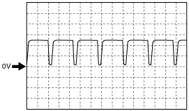
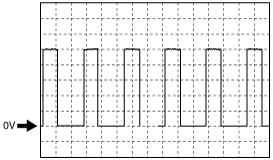
Inspection Using An Oscilloscope (Reference)
MAF sensor signal
am2zzw00002948
|
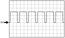
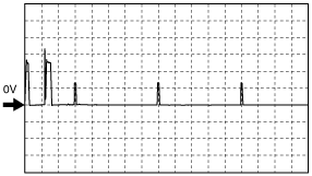
Fuel pressure ragulator signal
am2zzw00002949
|
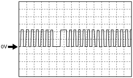
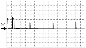
Fuel metering valve signal
am2zzw00002950
|
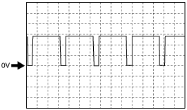
CKP sensor signal
am2zzw00002951
|
EGR valve actuator signal
am2zzw00002952
|
TP sensor signal
am2zzw00002953
|
CMP sensor signal
am2zzw00002954
|
Fuel injector (+) signal
am2zzw00003096
|
Fuel injector (-) signal
am2zzw00003097
|
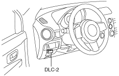
Using the M-MDS
1. Connect the M-MDS to the DLC-2.
am2zzw00003091
|
2. Turn the ignition switch to the ON position.
3. Measure the PID value.
PID monitor table (reference)
|
Item (Definition) |
Unit/ Condition |
Condition/Specification (Reference) |
Inspection item(s) |
PCM terminal |
|||
|---|---|---|---|---|---|---|---|
|
AC_PRES
|
V
|
A/C switch ON: Approx. 1.9 V
A/C switch OFF: Approx. 1.7 V
|
• A/C pressure sensor
|
3F
|
|||
|
Pa
|
A/C switch ON: Approx. 1.1 MPa
A/C switch OFF: Approx. 1.7 MPa
|
||||||
|
AC_REQ
|
Off/On
|
A/C switch ON: On
A/C switch OFF: Off
|
• A/C relay
|
1W
|
|||
|
ACCS
|
Off/On
|
A/C switch ON: On
A/C switch OFF: Off
|
• Inspect following PIDs:
AC_REQ, APP1, APP2, ECT, RPM
|
1W
|
|||
|
ALTF
|
%
|
Idle: Approx. 35—38 %
Ignition switch ON: 0 %
|
• Inspect following PIDs:
IAT, ECT, RPM, VPWR
|
2AK
|
|||
|
APP1
|
V
|
Accelerator pedal released: Approx. 0.39 V
Accelerator pedal depressed: Approx. 3.3 V
|
• APP sensor
|
3R
|
|||
|
%
|
Accelerator pedal released: 0 %
Accelerator pedal depressed: 99.6 %
|
||||||
|
APP2
|
%
|
Accelerator pedal released: 0 %
Accelerator pedal depressed: 99.6 %
|
—
|
||||
|
BARO
|
Pa
|
Indicate Barometric pressure.
|
• BARO sensor
|
—
|
|||
|
BAT
|
°C
|
°F
|
Indicates the Intake air temperature.
|
• IAT sensor No.2
|
1G
|
||
|
BAT_V
|
V
|
BAT 40 °C {104 °F}: Approx. 2.7 V
BAT 45 °C {113 °F}: Approx. 2.5 V
BAT 60 °C {140 °F}: Approx. 1.8 V
|
|||||
|
BOO
|
Off/On
|
Brake pedal released: Off
Brake pedal depressed: On
|
• Brake switch
|
3Y
|
|||
|
BPA
|
Off/On
|
Brake pedal released: Off
Brake pedal depressed: On
|
• BPP switch
|
—
|
|||
|
CPP
|
Off/On
|
Clutch pedal released: Off
Clutch pedal depressed: On
|
• CPP switch
|
—
|
|||
|
ECT
|
V
|
ECT 30 °C {86 °F}: Approx. 2.6 V
ECT 50 °C {122 °F}: Approx. 1.7 V
ECT 60 °C {140 °F}: Approx. 1.4 V
ECT 80 °C {176 °F}: Approx. 0.8 V
|
• ECT senosr
|
1C
|
|||
|
°C
|
°F
|
Indicates the engine coolant temperature.
|
|||||
|
EGRP
|
V
|
Idle: Approx. 2 V
Ignition switch ON: Approx. 0.96 V
|
• EGR valve
|
2O
|
|||
|
%
|
Idle: Approx. 40 %
Ignition switch ON: Approx. 0 %
|
||||||
|
ENG_TORQ
|
N·m
|
Indicates the engine torque
|
—
|
—
|
|||
|
ETC_DSD
|
%
|
Idle: Approx. 5 %
Ignition switch ON: Approx. 85.3 %
|
• Throttle position sensor
|
2AU
|
|||
|
FAN1
|
Off/On
|
Cooling fan relay No.1 opening: On
Cooling fan relay No.1 not opening: Off
|
• Cooling fan raley No.1
|
1S
|
|||
|
FAN2
|
Off/On
|
Cooling fan relay No.3 opening: On
Cooling fan relay No.3 not opening: Off
|
• Cooling fan raley No.3
|
1K
|
|||
|
FLI
|
%
|
Fuel level is display
|
—
|
—
|
|||
|
FLT
|
°C
|
°F
|
Fuel temperature is display
|
• Fuel temperature seonsor
|
2AF
|
||
|
FRP
|
V
|
Idle: Approx. 1.1 V
Ignition switch ON: Approx. 0.5 V
|
• Fuel pressure sensor
|
2T
|
|||
|
Pa
|
Idle: Approx. 25 MPa
Ignition switch ON: Approx. 2 MPa
|
||||||
|
FUEL_PCV
|
%
|
Idle: Approx. 13 %
Ignition switch ON: Approx. 0 %
|
• Fuel pressure regulator
|
1AA
|
|||
|
A
|
Idle: Approx. 200 mA
Ignition switch ON: Approx. 230 mA
|
||||||
|
FUEL_VCV
|
%
|
Idle: Approx. 23 %
Ignition switch ON: Approx. 0 %
|
• Fuel metering valve
|
1AB
|
|||
|
GPC
|
Off/On
|
Glow plug relay opening: On
Glow plug relay not opening: Off
|
• Glow plug relay
|
1O
|
|||
|
GPC_MON
|
Off/On
|
Glow plug relay opening: On
Glow plug relay not opening: Off
|
• Glow plug relay
|
3AC
|
|||
|
IAT
|
V
|
29 °C {84 °F}: Approx. 2.2 V
33 °C {91 °F}: Approx. 1.8 V
44 °C {111 °F}: Approx. 1.5 V
|
• IAT sensor
|
2X
|
|||
|
°C
|
°F
|
Intake air temperature is display
|
|||||
|
INJ_1
|
Off/On
|
Idle: On
Ignition switch ON: Off
|
• Fuel injectior No.1
|
3AR
|
|||
|
INJ_2
|
Off/On
|
Idle: On
Ignition switch ON: Off
|
• Fuel injectior No.2
|
3AQ
|
|||
|
INJ_3
|
Off/On
|
Idle: On
Ignition switch ON: Off
|
• Fuel injectior No.3
|
3AP
|
|||
|
INJ_4
|
Off/On
|
Idle: On
Ignition switch ON: Off
|
• Fuel injectior No.4
|
3AO
|
|||
|
INJ1_COR
|
—
|
Cylinder Balancing Offset Injector 1
|
• Fuel injectior No.1
|
3AR
|
|||
|
INJ2_COR
|
—
|
Cylinder Balancing Offset Injector 2
|
• Fuel injectior No.2
|
3AQ
|
|||
|
INJ3_COR
|
—
|
Cylinder Balancing Offset Injector 3
|
• Fuel injectior No.3
|
3AP
|
|||
|
INJ4_COR
|
—
|
Cylinder Balancing Offset Injector 4
|
• Fuel injectior No.4
|
3AO
|
|||
|
IVS
|
Idle / Off Idle
|
Idle: Idle
Except above: Off idle
|
• APP sensor
|
—
|
|||
|
LOW_OIL
|
Yes/No
|
Engine oil level status is displayed.
|
—
|
—
|
|||
|
MAF
|
g/sec
|
Idle: 6 g/sec
|
• MAF sensor
|
1I
|
|||
|
MAP
|
Pa
|
Bar
|
psi
|
Manifold absolute pressure is displayed.
|
• MAP sensor
|
2S
|
|
|
MIL_DIS
|
Km
|
Indicate the travelled distance since the MIL illuminated.
|
—
|
—
|
|||
|
RPM
|
RPM
|
Approx. 750 rpm
|
• CKP sensor
|
2L
|
|||
|
SEGRP DSD
|
%
|
Indicate the EGR valve position desired.
|
• EGR valve
|
2O
|
|||
|
VPWR
|
V
|
Ignition switch ON: B+
|
• Battery
• Main relay
|
1L
|
|||
|
VSS
|
KPH
|
Vehicle speed is displayed.
|
—
|
—
|
|||