 |
am2zzw00002571
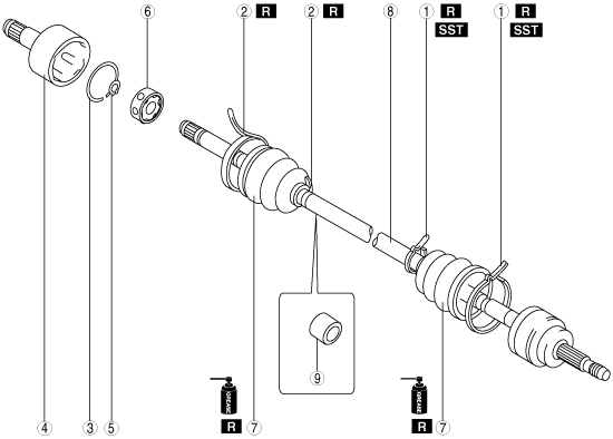
DRIVE SHAFT (MTX) DISASSEMBLY/ASSEMBLY
id031300152300
1. Disassemble in the order indicated in the table.
2. Assemble in the reverse order of disassembly.
am2zzw00002571
|
|
1
|
Boot band (wheel side)
|
|
2
|
Boot band (transaxle side)
|
|
3
|
Clip
(See Clip Disassembly Note.)
|
|
4
|
Outer ring
(See Outer Ring Assembly Note.)
|
|
5
|
Snap ring
(See Clip Disassembly Note.)
|
|
6
|
Balls, inner ring, cage
|
|
7
|
Boot
(See Boot Disassembly Note.)
(See Boot Assembly Note.)
|
|
8
|
Shaft and ball joint component
|
|
9
|
Dynamic damper (ZJ (LH), ZY (LH), MZ-CD 1.4 DI Turbo, MZ-CD 1.6 (Y6))
(See Dynamic Damper Assembly Note.)
|
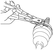
Boot Band (Wheel Side) Disassembly Note
1. Remove the boot band using an end clamp plier.
am2zzw00001972
|
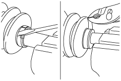
Boot Band (Transaxle Side) Disassembly Note
1. Pry up the points indicated in the figure using a plier, and remove the boot band.
am2zzw00001973
|
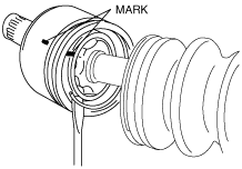
Clip Disassembly Note
1. Mark the drive shaft and outer ring for proper assembly.
am2zzw00001437
|
2. Remove the clip.
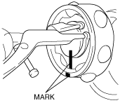
Snap Ring Disassembly Note
1. Mark the drive shaft end and inner ring for proper assembly.
am2zzw00001438
|
2. Remove the snap ring using a snap ring plier.
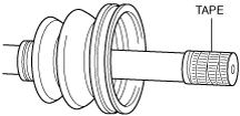
Boot Disassembly Note
1. Wrap the shaft splines with tape.
am2zzw00001975
|
2. Remove the boot.
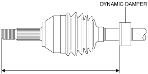
Dynamic Damper Assembly Note
1. Install the dynamic damper as shown in the figure.
am2zzw00003128
|
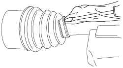
Boot Assembly Note
1. Fill the inside of the new dust boot (wheel side) with grease.
2. Install the boot with the splines of the shaft still wrapped in tape from disassembly.
3. Remove the tape.
Cage, Inner Ring, Balls, Snap Ring Assembly Note
1. Align the marks and install the inner ring to the shaft.
2. Install a new snap ring.
Outer Ring Assembly Note
1. Fill the outer ring and boot (transaxle side) with the specified grease.
2. Assemble the outer ring.
3. Set the drive shaft to the standard length.
Drive shaft length
|
|
ZJ, ZY |
MZ-CD 1.4 DI Turbo, MZ-CD 1.6 (Y6) |
|---|---|---|
|
LH
|
648.0—658.0 mm {25.52—25.90 in}
|
643.0—653.0 mm {25.32—25.70 in}
|
|
RH
|
589.4—599.4 mm {23.21—23.59 in}
|
560.5—570.5 mm {22.07—22.46 in}
|
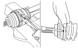
4. Release any trapped air from the boots by carefully lifting up the small end of each boot with a cloth wrapped screwdriver.
acxuuw00001300
|
5. Verify that the drive shaft length is within the standard under atmospheric pressure inside the boot.
Boot Band (Transaxle Side) Assembly Note
1. Pry up the points indicated in the figure using a plier, and tighten the boot band.
acxuuw00001250
|
Boot Band (Wheel Side) Assembly Note
Boot band (small diameter side)
1. Adjust clearance A by turning the adjusting bolt of the SST.
am2zzw00001442
|
2. Crimp the wheel side small boot band using the SST. Verify that clearance B is within the specification.
am2zzw00001443
|
3. Verify that the boot band does not protrude from the boot band installation area.
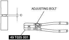
Boot band (Large diameter side)
1. Adjust clearance C by turning the adjusting bolt of the SST.
am2zzw00001444
|
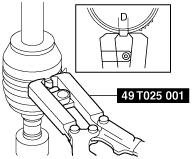
2. Crimp the wheel side large boot band using the SST. Verify that clearance D is within the specification.
am2zzw00003129
|
3. Verify that the boot band does not protrude from the boot band installation area.