ABS WHEEL-SPEED SENSOR AND ABS SENSOR ROTOR CONSTRUCTION/OPERATION
id041300185100
Construction
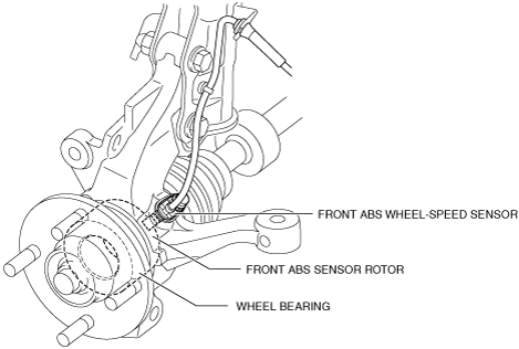
• The ABS wheel speed sensor utilizes a semiconductor element that contains an active drive circuit (MR element*). The front sensor is installed on the steering knuckle.The rear sensor is installed on the torsion beam axle.
• The ABS sensor rotor utilizes a magnetic encoder made of magnetic rubber. The front sensor rotor is integrated with the wheel bearing oil seal.The rear sensor rotor is pressed into the rear wheel bearing.
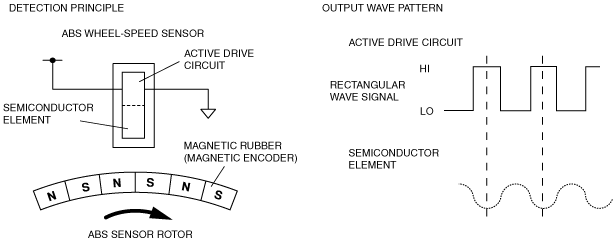
*: Magneto-resistive: A magneto-resistive force means that an exterior magnetic field acts on the element, changing the resistance of the element.
-
Caution
-
• When inspecting the ABS wheel speed sensor, do not use an ohmmeter to inspect resistance. It is possible that the voltage from the ohmmeter could damage the semiconductor inside the ABS wheel speed sensor.Inspect using the PID data monitor of the Mazda modular diagnostic system (M-MDS).
• When replacing the front wheel bearing, be careful of the direction in which the bearing is assembled.If the assembly direction is incorrect, the ABS sensor rotor cannot function.
-
Note
-
• Magnetic encoder: A plate that has positive and negative poles (marked out) in a continuous, alternating line.
ABS wheel-speed sensor and ABS sensor rotor (front)
ABS wheel speed sensor and ABS sensor rotor (rear)
Operation
• As the ABS sensor rotor rotates, the magnetic flux between the ABS wheel speed sensor and the ABS sensor rotor change periodically. This cycle change appears in proportion to the rotation speed.
• The semiconductor element in the wheel speed sensor detects the change in magnetic flux, and the active drive circuit converts it to a rectangular wave signal, which is transmitted to the ABS HU/CM.
• For every single rotation of the ABS sensor rotor, a 44-pulse rectangular wave signal is output.The CM in the ABS HU/CM calculates the wheel speed from the periodicity of these pulses.