 |
acmzzc00000028
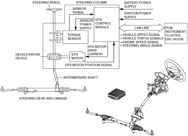
ELECTRIC POWER STEERING (EPS) CONSTRUCTION AND OPERATION
id061300246300
Construction
acmzzc00000028
|
Operation
Manual steering mechanism operation
Control system operation
Power assist mechanism operation
Component Parts and Function
|
Part name |
Function |
|
|---|---|---|
|
Steering wheel
|
• Transmits steering force from the driver to the steering column.
|
|
|
Steering column
|
Torque sensor
|
• Detects steering force and outputs it to the EPS control module as an electric signal.
|
|
EPS control module
|
• Control the current to the EPS motor based on the electric signals from the torque sensor and vehicle speed signals from the PCM.
• Controls the on-board diagnostic system and fail-safe function when a malfunction is detected in the EPS system.
• Transmits the steering angle signal via CAN lines to the DSC HU/CM.
|
|
|
EPS motor
|
• Generates drive force based on the target current from the EPS control module.
|
|
|
Reduction gear
|
• Transmits the drive force from the EPS motor to the intermediate shaft.
|
|
|
Intermediate shaft
|
• Transmits the drive force from the reduction gear to the steering gear and linkage.
|
|
|
Steering gear and linkage
|
• Transmits the drive force from the intermediate shaft to the wheels and tires.
|
|
|
PCM
|
• Outputs vehicle speed signal to the EPS control module via the CAN lines.
|
|
|
Instrument cluster
|
• Alerts the driver by illuminating/flashing the EPS warning according to the signals from the EPS control module if the EPS has a malfunction.
|
|