Part where malfunction is determined
Malfunction determined when IG SW at ON
Malfunction already exists when IG SW turned to ON
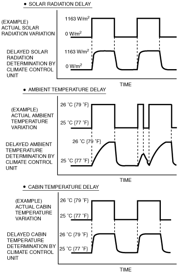
Solar radiation sensor
Solar radiation sensor input value is fixed at the value right before the malfunction.
Solar radiation sensor input value is fixed at 0 W/m2.
Cabin temperature sensor
Cabin temperature sensor input value is fixed at the value right before the malfunction.
Cabin temperature sensor input value is fixed at 25 °C {77 °F}.
Ambient temperature sensor
Ambient temperature sensor input value is fixed at the value right before the malfunction.
Ambient temperature sensor input value is fixed at 15°C {59 °F}.
Evaporator temperature sensor
Evaporator temperature sensor input value is fixed at 0 °C {32 °F}.
¨
ECT sensor
ECT sensor input value is fixed at 85 °C {185 °F}.
¨
Air mix actuator
(Potentiometer)
• Air mix actuator drive signal is stopped right after the malfunction is determined.
• However, it is fixed at MAX COLD when the manually set temperature is at 15 (left side of temperature setting dial) and fixed at MAX HOT when the manually set temperature is at 29 (right side of temperature setting dial).
Control based on ambient temperature.
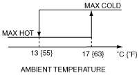
However, it is fixed at MAX COLD when the manually set temperature is at 15 (left side of temperature setting dial) and fixed at MAX HOT when the manually set temperature is at 29 (right side of temperature setting dial).
Airflow mode actuator
(Potentiometer)
• Airflow mode actuator drive signal is stopped right after the malfunction is determined.
• For manual operation using the mode dial, only vent or defroster mode is operable.
Control based on ambient temperature.
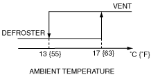
For manual operation using the mode dial, only vent or defroster mode is operable.
Air mix actuator
(Motor lock)
Air mix actuator drive signal is stopped right after the malfunction is determined.
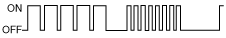
After this, a drive signal is output to the air mix actuator and malfunction determination is performed approx. every 5 min.
After the ignition switch is turned to the ON position, the air mix actuator drive signal is output normally again.
After this, a drive signal is output to the air mix actuator and malfunction determination is performed approx. every 5 min.
Airflow mode actuator
(Motor lock)
Airflow mode actuator drive signal is stopped right after the malfunction is determined.
After this, a drive signal is output to the airflow mode actuator and malfunction determination is performed approx. every 5 min.
After the ignition switch is turned to the ON position, the airflow mode actuator drive signal is output normally again.
After this, a drive signal is output to the airflow mode actuator and malfunction determination is performed approx. every 5 min.