 |
am2zzn00000942
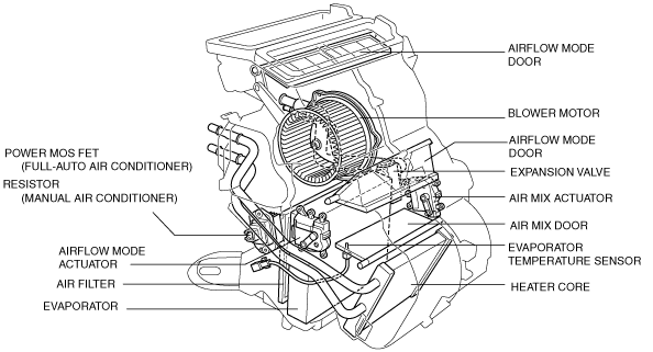
A/C UNIT CONSTRUCTION/OPERATION
id071100100400
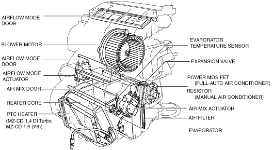
Construction
L.H.D.
am2zzn00000942
|
R.H.D.
am2zzn00000281
|
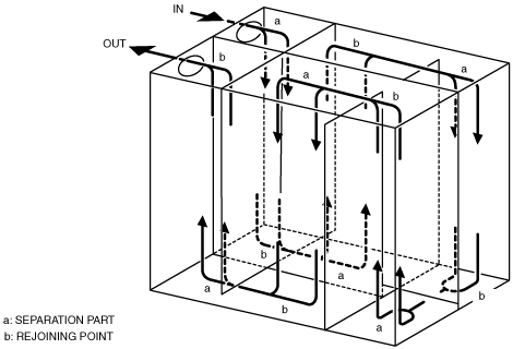
Evaporator
am2zzn00000268
|
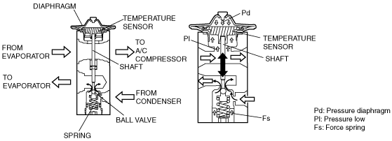
Expansion valve
acxuun00000157
|
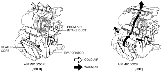
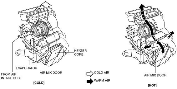
Operation
Air mix door
L.H.D.
am2zzn00000269
|
R.H.D.
am2zzn00000282
|
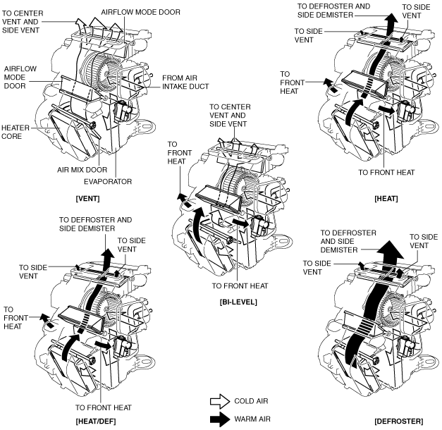
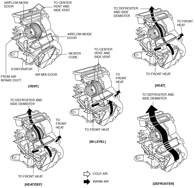
Airflow mode door
L.H.D.
am2zzn00000283
|
R.H.D.
am2zzn00000284
|
L.H.D.
|
Airflow mode |
Airflow volume ratio* (%) (Approx. quantity) |
||||||||||||
|---|---|---|---|---|---|---|---|---|---|---|---|---|---|
|
VENT |
HEAT |
DEFROSTER |
|||||||||||
|
Driver side |
Passenger side |
Total |
Driver side |
Passenger side |
Total |
Driver side |
Passenger side |
Total |
|||||
|
Side |
Center |
Side |
Center |
Side |
Center |
Side |
Center |
||||||
|
VENT
|
25
|
25
|
25
|
25
|
100
|
—
|
—
|
—
|
—
|
—
|
—
|
—
|
—
|
|
BI-LEVEL
|
16.25
|
16.25
|
16.25
|
16.25
|
65
|
17.5
|
17.5
|
35
|
—
|
—
|
—
|
—
|
—
|
|
HEAT
|
5
|
—
|
—
|
5
|
10
|
35
|
35
|
70
|
10
|
10
|
20
|
||
|
HEAT/DEF
|
7.5
|
—
|
—
|
7.5
|
15
|
20
|
20
|
40
|
22.5
|
22.5
|
45
|
||
|
DEFROSTER
|
10
|
—
|
—
|
10
|
20
|
—
|
—
|
—
|
40
|
40
|
80
|
||
R.H.D.
|
Airflow mode |
Airflow volume ratio* (%) (Approx. quantity) |
||||||||||||
|---|---|---|---|---|---|---|---|---|---|---|---|---|---|
|
VENT |
HEAT |
DEFROSTER |
|||||||||||
|
Driver side |
Passenger side |
Total |
Driver side |
Passenger side |
Total |
Driver side |
Passenger side |
Total |
|||||
|
Side |
Center |
Side |
Center |
Side |
Center |
Side |
Center |
||||||
|
VENT
|
25
|
25
|
25
|
25
|
100
|
—
|
—
|
—
|
—
|
—
|
—
|
—
|
—
|
|
BI-LEVEL
|
16.25
|
16.25
|
16.25
|
16.25
|
65
|
17.5
|
17.5
|
35
|
—
|
—
|
—
|
—
|
—
|
|
HEAT
|
—
|
—
|
—
|
—
|
—
|
40
|
40
|
80
|
10
|
10
|
20
|
||
|
HEAT/DEF
|
—
|
—
|
—
|
—
|
—
|
20
|
20
|
40
|
30
|
30
|
60
|
||
|
DEFROSTER
|
—
|
—
|
—
|
—
|
—
|
—
|
—
|
—
|
50
|
50
|
100
|
||