 |
am2zzw00001015
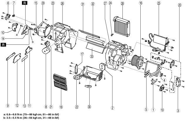
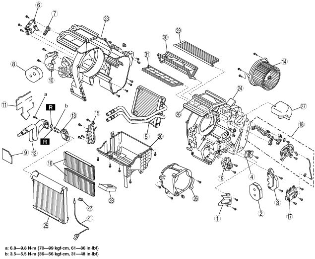
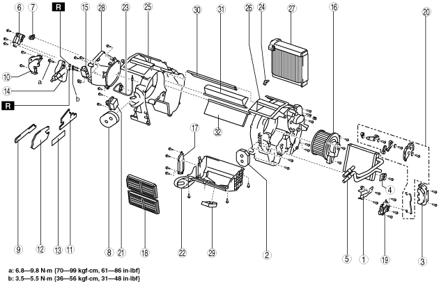
A/C UNIT DISASSEMBLY/ASSEMBLY
id071100800300
L.H.D.
1. Disassemble in the order indicated in the figure.
2. Assemble in the reverse order of disassembly.
Full-auto Air Conditioner (ZJ, ZY)
am2zzw00001015
|
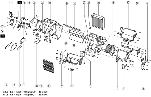
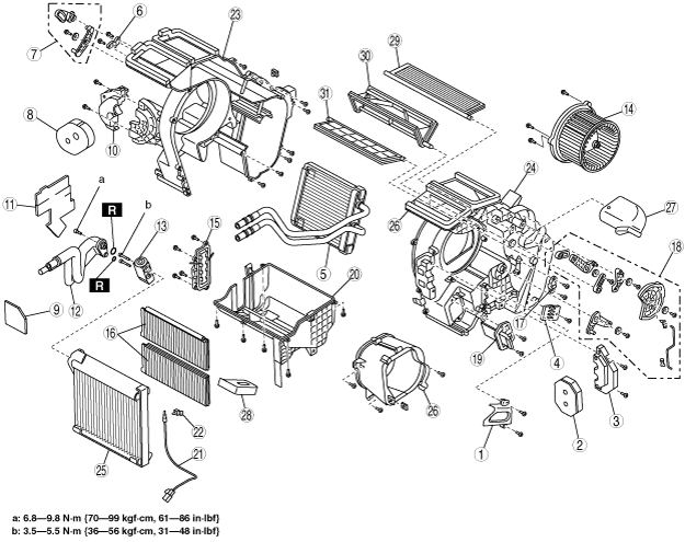
Full-auto Air Conditioner (MZ-CD 1.4 DI Turbo, MZ-CD 1.6 (Y6))
am2zzw00002962
|
|
Step |
Part name |
Disassembly/assembly of main parts |
||
|---|---|---|---|---|
|
Heater core |
Evaporator temperature sensor |
Evaporator |
||
|
1
|
Heater pipe cover
|
X
|
−
|
−
|
|
2
|
Polyurethane foam (1)
|
X
|
−
|
−
|
|
3
|
Heater pipe bracket
|
X
|
−
|
−
|
|
4
|
Heater core stopper
|
X
|
−
|
−
|
|
5
|
Heater core
|
X
|
−
|
−
|
|
6
|
Air mix actuator
|
−
|
−
|
−
|
|
7
|
Air mix link set
|
−
|
−
|
−
|
|
8
|
Polyurethane foam (2)
|
−
|
−
|
X
|
|
9
|
Adhesive polyurethane (3)
|
−
|
−
|
X
|
|
10
|
Outlet pipe bracket
|
−
|
−
|
X
|
|
11
|
Adhesive polyurethane (2)
|
−
|
−
|
X
|
|
12
|
Adhesive polyurethane (1)
|
−
|
−
|
X
|
|
13
|
Insulator
|
−
|
−
|
X
|
|
14
|
Outlet pipe
(See Outlet pipe removal note.)
|
−
|
−
|
X
|
|
15
|
Expansion valve
|
−
|
−
|
X
|
|
16
|
Blower motor
|
−
|
−
|
X
|
|
17
|
Cover
|
−
|
X
|
X
|
|
18
|
Air filter
|
−
|
X
|
X
|
|
19
|
Airflow mode actuator
|
−
|
−
|
−
|
|
20
|
Airflow mode link set
|
−
|
−
|
−
|
|
21
|
Power MOS FET
|
−
|
−
|
−
|
|
22
|
A/C case (3)
|
−
|
X
|
X
|
|
23
|
Evaporator temperature sensor
|
−
|
X
|
X
|
|
24
|
Sensor clamp
(See Sensor clamp assembly note.)
|
−
|
X
|
X
|
|
25
|
PTC heater (MZ-CD 1.4 DI Turbo, MZ-CD 1.6 (Y6))
|
−
|
−
|
−
|
|
26
|
A/C case (1)
(See A/C case disassembly note.)
|
−
|
−
|
X
|
|
27
|
A/C case (2)
(See A/C case disassembly note.)
|
−
|
−
|
X
|
|
28
|
Evaporator
|
−
|
−
|
X
|
|
29
|
A/C case (4)
|
−
|
−
|
−
|
|
30
|
Polyurethane foam (3)
|
−
|
−
|
−
|
|
31
|
Airflow mode door (1)
|
−
|
−
|
−
|
|
32
|
Airflow mode door (2)
|
−
|
−
|
−
|
|
33
|
Air mix door
|
−
|
−
|
−
|
Manual air conditioner (ZJ, ZY)
am2zzw00001016
|
Manual air conditioner (MZ-CD 1.4 DI Turbo, MZ-CD 1.6 (Y6))
am2zzw00002963
|
|
Step |
Part name |
Disassembly/assembly of main parts |
||
|---|---|---|---|---|
|
Heater core |
Evaporator temperature sensor |
Evaporator |
||
|
1
|
Heater pipe cover
|
X
|
−
|
−
|
|
2
|
Polyurethane foam (1)
|
X
|
−
|
−
|
|
3
|
Heater pipe bracket
|
X
|
−
|
−
|
|
4
|
Heater core stopper
|
X
|
−
|
−
|
|
5
|
Heater core
|
X
|
−
|
−
|
|
6
|
Wire clamp
|
−
|
−
|
−
|
|
7
|
Air mix link set
|
−
|
−
|
−
|
|
8
|
Polyurethane foam (2)
|
−
|
−
|
X
|
|
9
|
Adhesive polyurethane (3)
|
−
|
−
|
X
|
|
10
|
Outlet pipe bracket
|
−
|
−
|
X
|
|
11
|
Adhesive polyurethane (2)
|
−
|
−
|
X
|
|
12
|
Adhesive polyurethane (1)
|
−
|
−
|
X
|
|
13
|
Insulator
|
−
|
−
|
X
|
|
14
|
Outlet pipe
(See Outlet pipe removal note.)
|
−
|
−
|
X
|
|
15
|
Expansion valve
|
−
|
−
|
X
|
|
16
|
Blower motor
|
−
|
−
|
X
|
|
17
|
Cover
|
−
|
X
|
X
|
|
18
|
Air filter
|
−
|
X
|
X
|
|
19
|
Wire clamp
|
−
|
−
|
−
|
|
20
|
Airflow mode link set
|
−
|
−
|
−
|
|
21
|
Resistor
|
−
|
−
|
−
|
|
22
|
A/C case (3)
|
−
|
X
|
X
|
|
23
|
Evaporator temperature sensor
|
−
|
X
|
X
|
|
24
|
Sensor clamp
(See Sensor clamp assembly note.)
|
−
|
X
|
X
|
|
25
|
PTC heater (MZ-CD 1.4 DI Turbo, MZ-CD 1.6 (Y6))
|
−
|
−
|
−
|
|
26
|
A/C case (1)
(See A/C case disassembly note.)
|
−
|
−
|
X
|
|
27
|
A/C case (2)
(See A/C case disassembly note.)
|
−
|
−
|
X
|
|
28
|
Evaporator
|
−
|
−
|
X
|
|
29
|
A/C case (4)
|
−
|
−
|
−
|
|
30
|
Polyurethane foam (3)
|
−
|
−
|
−
|
|
31
|
Airflow mode door (1)
|
−
|
−
|
−
|
|
32
|
Airflow mode door (2)
|
−
|
−
|
−
|
|
33
|
Air mix door
|
−
|
−
|
−
|
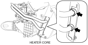
Heater core removal/installation note
am2zzw00002193
|
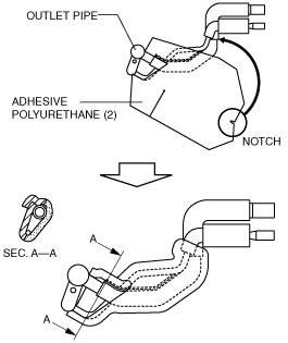
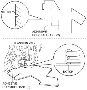
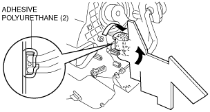
Adhesive polyurethane (1), (2) removal note
Outlet pipe removal note
1. Make a hole in the position shown in the figure for the adhesive polyurethane (2) and install the outlet pipe installation bolt.
am2zzw00001828
|
2. Tear off the adhesive polyurethane (2) from the joint area of the expansion valve and outlet pipe.
3. Remove the outlet pipe from the expansion valve.
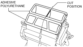
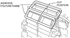
A/C case disassembly note
1. Cut the adhesive polyurethane along the contacting surfaces of the case.
am2zzw00001018
|
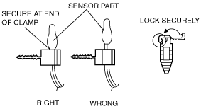
Sensor clamp assembly note
1. Install as shown in the figure.
acxuuw00000696
|
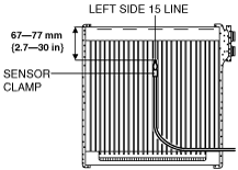
Evaporator temperature sensor assembly note
1. Install the evaporator temperature sensor as shown in the figure.
am2zzw00001061
|
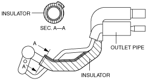
Adhesive polyurethane (1), (2) installation note
1. Wrap the low-pressure side of the outlet pipe with insulator.
am2zzw00001019
|
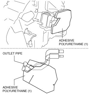
2. Attach the adhesive polyurethane (1) from the outlet pipe as shown in the figure.
am2zzw00001020
|
3. Roll the adhesive polyurethane (1) on to the outlet pipe so that the adhesive polyurethane (1) notch reaches the contact point between the outlet pipe sponge rubber and the insulator.
am2zzw00001021
|
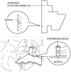
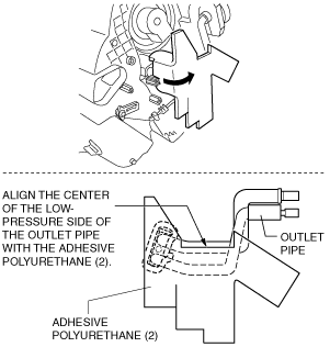
4. Align the adhesive polyurethane (2) notch with the center of the lower surface of the expansion valve, and adhere.
am2zzw00002013
|
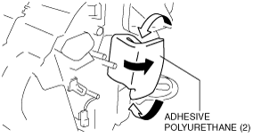
5. Roll on the adhesive polyurethane (2) so that it wraps around the expansion valve.
am2zzw00001829
|
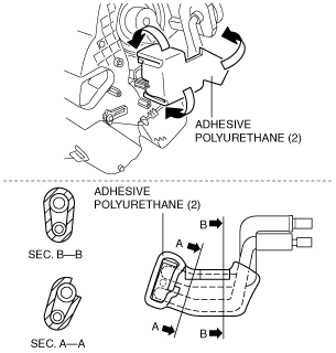
6. Bend around the adhesive polyurethane (2) and adhere it to the outlet pipe.
am2zzw00001830
|
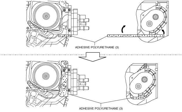
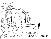
Adhesive polyurethane (3) installation note
1. Attach the adhesive polyurethane (3) as shown in the figure.
am2zzw00001025
|
R.H.D.
1. Disassemble in the order indicated in the figure.
2. Assemble in the reverse order of disassembly.
Full-auto Air Conditioner
am2zzw00001831
|
|
Step |
Part name |
Disassembly/assembly of main parts |
||
|---|---|---|---|---|
|
Heater core |
Evaporator temperature sensor |
Evaporator |
||
|
1
|
Heater pipe cover
|
X
|
−
|
−
|
|
2
|
Polyurethane foam (1)
|
X
|
−
|
−
|
|
3
|
Heater pipe bracket
|
X
|
−
|
−
|
|
4
|
Heater core stopper
|
X
|
−
|
−
|
|
5
|
Heater core
|
X
|
−
|
−
|
|
6
|
Air mix actuator
|
−
|
−
|
−
|
|
7
|
Air mix link set
|
−
|
−
|
−
|
|
8
|
Polyurethane foam (2)
|
−
|
−
|
X
|
|
9
|
Adhesive polyurethane (1)
|
−
|
−
|
X
|
|
10
|
Outlet pipe bracket
|
−
|
−
|
X
|
|
11
|
Adhesive polyurethane (2)
|
−
|
−
|
X
|
|
12
|
Outlet pipe
(See Outlet pipe removal note.)
|
−
|
−
|
X
|
|
13
|
Expansion valve
|
−
|
−
|
X
|
|
14
|
Blower motor
|
−
|
−
|
X
|
|
15
|
Cover
|
−
|
X
|
X
|
|
16
|
Air filter
|
−
|
X
|
X
|
|
17
|
Airflow mode actuator
|
−
|
−
|
−
|
|
18
|
Airflow mode link set
|
−
|
−
|
−
|
|
19
|
Power MOS FET
|
−
|
−
|
−
|
|
20
|
A/C case (3)
|
−
|
X
|
X
|
|
21
|
Evaporator temperature sensor
|
−
|
X
|
X
|
|
22
|
Sensor clamp
(See Sensor clamp assembly note.)
|
−
|
X
|
X
|
|
23
|
A/C case (1)
(See A/C case disassembly note.)
|
−
|
−
|
X
|
|
24
|
A/C case (2)
(See A/C case disassembly note.)
|
−
|
−
|
X
|
|
25
|
Evaporator
|
−
|
−
|
X
|
|
26
|
A/C case (4)
|
−
|
−
|
−
|
|
27
|
Heater duct
|
−
|
−
|
−
|
|
28
|
Polyurethane foam (3)
|
−
|
−
|
−
|
|
29
|
Airflow mode door (1)
|
−
|
−
|
−
|
|
30
|
Airflow mode door (2)
|
−
|
−
|
−
|
|
31
|
Air mix door
|
−
|
−
|
−
|
Manual air conditioner
am2zzw00001832
|
|
Step |
Part name |
Disassembly/assembly of main parts |
||
|---|---|---|---|---|
|
Heater core |
Evaporator temperature sensor |
Evaporator |
||
|
1
|
Heater pipe cover
|
X
|
−
|
−
|
|
2
|
Polyurethane foam (1)
|
X
|
−
|
−
|
|
3
|
Heater pipe bracket
|
X
|
−
|
−
|
|
4
|
Heater core stopper
|
X
|
−
|
−
|
|
5
|
Heater core
|
X
|
−
|
−
|
|
6
|
Wire clamp
|
−
|
−
|
−
|
|
7
|
Air mix actuator
|
−
|
−
|
−
|
|
8
|
Polyurethane foam (2)
|
−
|
−
|
X
|
|
9
|
Adhesive polyurethane (1)
|
−
|
−
|
X
|
|
10
|
Outlet pipe bracket
|
−
|
−
|
X
|
|
11
|
Adhesive polyurethane (2)
|
−
|
−
|
X
|
|
12
|
Outlet pipe
(See Outlet pipe removal note.)
|
−
|
−
|
X
|
|
13
|
Expansion valve
|
−
|
−
|
X
|
|
14
|
Blower motor
|
−
|
−
|
X
|
|
15
|
Cover
|
−
|
X
|
X
|
|
16
|
Air filter
|
−
|
X
|
X
|
|
17
|
Wire clamp
|
−
|
−
|
−
|
|
18
|
Airflow mode link set
|
−
|
−
|
−
|
|
19
|
Resistor
|
−
|
−
|
−
|
|
20
|
A/C case (3)
|
−
|
X
|
X
|
|
21
|
Evaporator temperature sensor
|
−
|
X
|
X
|
|
22
|
Sensor clamp
(See Sensor clamp assembly note.)
|
−
|
X
|
X
|
|
23
|
A/C case (1)
(See A/C case disassembly note.)
|
−
|
−
|
X
|
|
24
|
A/C case (2)
(See A/C case disassembly note.)
|
−
|
−
|
X
|
|
25
|
Evaporator
|
−
|
−
|
X
|
|
26
|
A/C case (4)
|
−
|
−
|
−
|
|
27
|
Heater duct
|
−
|
−
|
−
|
|
28
|
Polyurethane foam (3)
|
−
|
−
|
−
|
|
29
|
Airflow mode door (1)
|
−
|
−
|
−
|
|
30
|
Airflow mode door (2)
|
−
|
−
|
−
|
|
31
|
Air mix door
|
−
|
−
|
−
|
Heater core removal/installation note
am2zzw00002193
|
Adhesive polyurethane (1), (2) removal note
Outlet pipe removal note
1. Make a hole in the position shown in the figure for the adhesive polyurethane (2) and install the outlet pipe installation bolt.
am2zzw00001833
|
2. Tear off the adhesive polyurethane (2) from the joint area of the expansion valve and outlet pipe.
3. Remove the outlet pipe from the expansion valve.
A/C case disassembly note
1. Cut the adhesive polyurethane along the contacting surfaces of the case.
am2zzw00001834
|
Sensor clamp assembly note
1. Install as shown in the figure.
acxuuw00000696
|
Evaporator temperature sensor assembly note
1. Install the evaporator temperature sensor as shown in the figure.
adejjw00003519
|
Adhesive polyurethane (2) installation note
1. Align the adhesive polyurethane (2) notch with the center of the lower surface of the expansion valve, and adhere.
am2zzw00002014
|
2. Roll on the adhesive polyurethane (2) so that it wraps around the expansion valve.
am2zzw00001835
|
3. Bend around the adhesive polyurethane (2) and adhere it to the side surface of the outlet pipe.
am2zzw00002015
|
4. Roll the adhesive polyurethane (2) on to the outlet pipe as shown in the figure.
am2zzw00001836
|
Adhesive polyurethane (1) installation note
1. Attach the adhesive polyurethane (1) as shown in the figure.
am2zzw00001837
|