 |
am2zzn00000445
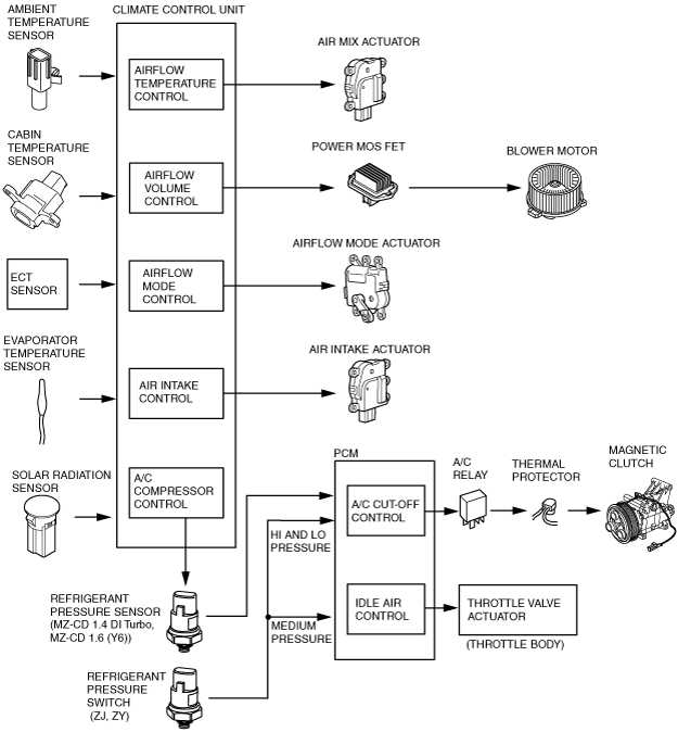
FULL-AUTO AIR CONDITIONER FUNCTION [FULL-AUTO AIR CONDITIONER]
id0740a1100600
Block Diagram
am2zzn00000445
|
Control Table
|
Basic Control |
Control description |
Correction control |
|---|---|---|
|
Airflow temperature control
|
Airflow temperature automatic control
|
• Air intake correction
• A/C correction
• MAX HOT and MAX COLD correction
• Water temperature correction
|
|
Airflow volume control
|
Airflow volume automatic control
|
• Water temperature correction (Warm-up correction)
• Mild start correction
• MAX HOT and MAX COLD correction
• Window fogging prevention correction at start
• Starting compensation correction
• Defroster correction
• Start-up burn-out prevention function
|
|
Airflow volume manual control
|
• Defroster correction
• Excess current prevention function during start-up
|
|
|
Airflow mode control
|
Airflow mode automatic control
|
• Water temperature correction (Warm-up correction)
|
|
Airflow mode manual control
|
―
|
|
|
Air intake control
|
Air intake manual control
|
• Defroster correction
|
|
A/C compressor control
|
A/C compressor automatic control
|
• Defroster correction
• Ambient temperature correction
• MAX COLD correction
• Window fogging prevention correction at start
|
|
A/C compressor manual control
|
• Defroster correction
• Ambient temperature correction
• Window fogging prevention correction at start
|
|
Supplementary function |
|---|
|
Fail-safe function
|
|
Sensor signal delay function
|
|
On-board Diagnostic Function
|
Control Transition by Switch Operation
Airflow temperature control, airflow volume control
|
Operation switch |
Airflow temperature control |
Airflow volume control |
||||
|---|---|---|---|---|---|---|
|
Control before switch operation |
Control before switch operation |
|||||
|
Automatic control |
Automatic control |
Automatic control (Defroster correction) |
Manual control |
OFF |
||
|
Airflow volume control dial
|
OFF
|
Automatic control
|
OFF
|
OFF
|
OFF
|
―
|
|
AUTO
|
Automatic control
|
―
|
―
|
Automatic control
|
Automatic control
|
|
|
Manual
|
Automatic control
|
Manual control
|
Manual control
|
―
|
Manual control
|
|
|
Airflow mode control dial
|
AUTO
|
Automatic control
|
Automatic control
|
Automatic control
(Defroster correction cancel)
|
No change
|
No change
|
|
Vent
|
Automatic control
|
Automatic control
|
Automatic control
(Defroster correction cancel)
|
No change
|
No change
|
|
|
BI-LEVEL
|
Automatic control
|
Automatic control
|
Automatic control
(Defroster correction cancel)
|
No change
|
No change
|
|
|
HEAT
|
Automatic control
|
Automatic control
|
Automatic control
(Defroster correction cancel)
|
No change
|
No change
|
|
|
HEAT/DEF
|
Automatic control
|
Automatic control
|
Automatic control
(Defroster correction cancel)
|
No change
|
No change
|
|
|
DEFROSTER
|
Automatic control
|
Defroster correction
|
―
|
No change
|
No change
|
|
|
A/C switch
|
Automatic control
|
Automatic control
|
No change
|
No change
|
No change
|
|
|
REC/FRESH switch
|
Automatic control
|
Automatic control
|
No change
|
No change
|
No change
|
|
|
Temperature setting dial
|
15 (left end)*2/
18 (left end)*3
|
MAX COLD
|
MAX HI
|
MAX HI
|
No change
|
No change
|
|
16—28*2/
19—31*3
|
Automatic control
|
Automatic control
|
Defroster correction
|
No change
|
No change
|
|
|
29 (right end)*2/
32 (right end)*3
|
MAX HOT
|
AUTO HI*1
|
AUTO HI
|
No change
|
No change
|
|
Airflow mode control, air intake control, A/C compressor control
|
Operation switch |
Airflow mode control |
Air intake control |
A/C compressor control |
|||
|---|---|---|---|---|---|---|
|
Control before switch operation |
Control before switch operation |
Control before switch operation |
||||
|
Automatic control |
Manual control |
Manual control |
Automatic control |
OFF |
||
|
Airflow volume control dial
|
OFF
|
Fixed at mode prior to fan OFF
|
No change
|
No change
|
OFF
|
OFF
|
|
AUTO
|
Automatic control
|
No change
|
No change
|
Automatic control
|
No change
|
|
|
Manual
|
Automatic control
|
No change
|
No change
|
Automatic control
|
No change
|
|
|
Airflow mode control dial
|
AUTO
|
―
|
Automatic control
|
No change *2
|
Auto control *3
|
No change *3
|
|
VENT
|
VENT
|
VENT
|
No change *2
|
Auto control *3
|
No change *3
|
|
|
BI-LEVEL
|
BI-LEVEL
|
BI-LEVEL
|
No change*2
|
Auto control *3
|
No change*3
|
|
|
HEAT
|
HEAT
|
HEAT
|
No change*2
|
Auto control *3
|
No change*3
|
|
|
HEAT/DEF
|
HEAT/DEF
|
HEAT/DEF
|
No change*2
|
Auto control *3
|
No change*3
|
|
|
Defroster
|
DEFROSTER
|
DEFROSTER
|
Defroster correction
|
Defroster correction
|
Defroster correction
|
|
|
A/C switch
|
Automatic control
|
No change
|
No change
|
OFF
|
Automatic control
|
|
|
REC/FRESH switch
|
Automatic control
|
No change
|
RECIRCULATE→FRESH
FRESH→RECIRCULATE
|
Automatic control
|
No change
|
|
|
Temperature setting dial
|
15 (left end)*4/
18 (left end)*5
|
Automatic control*1
|
No change
|
No change
|
Automatic control
|
No change
|
|
16—28*4/
19—31*5
|
Automatic control*1
|
No change
|
No change
|
Automatic control
|
No change
|
|
|
29 (right end)*4/
32 (right end)*5
|
Automatic control*1
|
No change
|
No change
|
Automatic control
|
No change
|
|