 |
am2zzw00002084
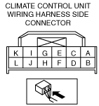
CLIMATE CONTROL UNIT INSPECTION [MANUAL AIR CONDITIONER]
id0740a2802200
1. Remove the climate control unit with the connector connected. (See CLIMATE CONTROL UNIT REMOVAL/INSTALLATION [MANUAL AIR CONDITIONER].)
2. Turn the ignition switch to the ON position.
3. Connect the negative (-) lead of the tester to the body ground.
4. By inserting the positive (+) lead of the tester into the climate control unit connector, measure the voltage according to the terminal voltage table.
am2zzw00002084
|
Terminal Voltage Table (Reference)
|
Terminal |
Signal name |
Connected to |
Measurement condition |
Voltage (V) |
Inspection item(s) |
|
|---|---|---|---|---|---|---|
|
A
|
TNS (+)
|
TNS relay (BCM)
|
Light switch off
|
1.0 or less
|
• Light switch
• TNS relay
• BCM
• Related wiring harness
|
|
|
Light switch on
(TNS, headlight)
|
B+
|
|||||
|
B
|
IG2
|
• Ignition switch
• A/C 7.5 A fuse
|
Ignition switch in ON position
|
B+
|
• Ignition switch
• A/C 7.5 A fuse
• Related wiring harness
|
|
|
Ignition switch in LOCK position
|
1.0 or less
|
|||||
|
C
|
―
|
―
|
―
|
―
|
―
|
|
|
D
|
―
|
―
|
―
|
―
|
―
|
|
|
E
|
TNS (-)
|
Body ground
|
Under any condition
|
1.0 or less
|
• Related wiring harness
|
|
|
Panel light control input
|
Instrument cluster
|
Headlight ON and panel light control MAX
|
2.0
|
• Instrument cluster
• Related wiring harness
|
||
|
Headlight ON and panel light control MIN
|
10.2
|
|||||
|
F
|
Ground
|
Body ground
|
Under any condition
|
1.0 or less
|
• Related wiring harness
|
|
|
G
|
Rear window defroster indicator output
|
BCM
|
Ignition switch in ON position
|
Rear window defroster on
|
1.0 or less
|
• BCM
• Related wiring harness
|
|
Rear window defroster off
|
9.8
|
|||||
|
H
|
―
|
―
|
―
|
―
|
―
|
|
|
I
|
Rear window defroster operation
|
BCM
|
Ignition switch in ON position
|
Rear window defroster switch off
|
1.5
|
• BCM
• Related wiring harness
|
|
Rear window defroster switch held on
|
1.0 or less
|
|||||
|
J*2
|
PTC request
|
Instrument cluster
|
Ignition switch in ON position
|
Fan stopped
|
4.5
|
• Instrument cluster
• Related wiring harness
|
|
Fan switch on
|
1.0 or less
|
|||||
|
K*1
|
A/C
|
• Refrigerant pressure switch
• PCM
|
Ignition switch in ON position
|
Fan stopped
|
4.5
|
• Refrigerant pressure switch
• PCM
• Related wiring harness
|
|
Fan switch on and A/C switch on
|
1.0 or less
|
|||||
|
K*2
|
A/C
|
Instrument cluster
|
Ignition switch in ON position
|
Fan stopped
|
5.0
|
• Instrument cluster
• Related wiring harness
|
|
Fan switch on and A/C switch on
|
1.0 or less
|
|||||
|
L
|
Blower fan on/off
|
• Fan switch
• Resistor
|
Ignition switch in ON position
|
Fan stopped
|
B+
|
• Fan switch
• Resistor
• Related wiring harness
|
|
Fan switch on
|
1.0 or less
|
|||||